
We have the HOTSTART Certification for technicians who want to learn the proper installation procedure for HOTflow ™ heaters.

The TPS model is available in 0.5, 1.5, 1.8 and 2.0kW. It can heat generators up to 400kVA. Installation Instructions
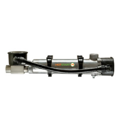
The CB, CL and WL models are available in powers of 1.5 to 6kW. Can heat generators of 400-800kVA. Installation Instructions
The CTM model is available in powers of 1, 1.5 and 2.5kW. Can heat generators up to 800kVA. Installation Instructions
The WL model (three phase and with electrical connection) is available in powers between 1.5 to 5kW. It circulates refrigerante through motors of between 4,9 and 27L. Installation Instructions

The CSM model is available in powers of 3, 6, 9 and 12kW. It can heat generators of 800-3500kVA. Installation Instructions
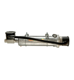
The SB and SL thermosiphon type cast aluminum heaters are designed to circulate the coolant through motors with sizes from 3 liters to 22 liters.

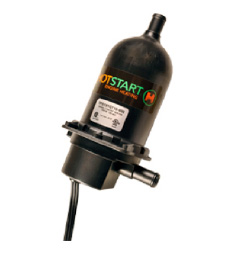
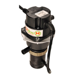
The HOTflow® CKM motor heater is a refrigerant preheater that has a mechanical pump integrated directly into the stainless steel heating tank, which maximizes the flow and minimizes the footprint of the heater at the same time.
Our daily lives have become dependent on having power readily available 24 hours a day, seven days a week. Critical facilities such as hospitals, banks, transit authorities, gas stations, hotels, cell phone towers, high rise buildings and others depend on backup power in emergencies to keep their operations going. In an emergency, backup generators in these types of applications must start and accept full load power within ten seconds. HOTSTART engine heaters make that happen.
Heating coolant and keeping it circulating in an engine block when it is in standby mode keeps the generator ready to start at a moment's notice. HOTSTART’s wide range of heating solutions for generators includes traditional convection-based heating systems as well as efficient pump-driven models. Ensure your facility is ready to stay powered when it matters most with HOTSTART heaters.
Heaters for forced circulation hot melt heaters
Constant coolant circulation eliminates hot spots that damage heater hoses, damage engine seals and reduce coolant life. Forced circulation heaters, such as HOTflow ™ heaters, use an integrated pump to circulate the coolant through the engine to keep it at a more even temperature than standard convection heaters.
Our Service “Certified Technician of HOTSTART”
We have the HOTSTART Certification for technicians who want to learn the proper installation procedure for HOTflow ™ heaters.
Diesel Generators Heaters.
The great variety of preheater we have in our inventories allows us to offer our customers fast deliveries and the correct recommendation which type of preheater corresponds according to the capacity of your Engine.
TPS Model
The TPS model is available in 0.5, 1.5, 1.8 and 2.0kW. It can heat generators up to 400kVA.
Installation Instructions please send us Whats App (305) 790 9489 for the USA market and Caribbean Islands
CB, CL y WL Models
The CB, CL and WL models are available in the range of 1.5 to 6kW. Can heat generators of 400-800kVA. Please see the Installation Instructions.
CTM Models
The CTM model is available in powers of 1, 1.5 and 2.5kW. Can heat generators up to 800kVA. Installation Instructions
WS Model
The WL model (three phase and with electrical connection) is available in powers between 1.5 to 5kW. of between 4,9 and 27L. Installation Instructions
CSM Models
The CSM model is available in powers of 3, 6, 9 and 12kW. It can heat generators of 800-3500kVA. Installation Instructions
SB y SL Models
The SB and SL thermosiphon type cast aluminum heaters are designed to circulate the coolant through motors with sizes from 3 liters to 22 liters.
HOTflow® CKM Model
The HOTflow® CKM motor heater is a refrigerant preheater that has a mechanical pump integrated directly into the stainless steel heating tank, which maximizes the flow and minimizes the footprint of the heater at the same time.
HOTflow® and THERMOSIPHON ENGINE HEATERS
HOTflow®
Engine Displacement CID/Liter | Power Supply Volts Ø Hz | kW | Amps | Model Number |
Engine Heaters
CTM Model Single Phase
1000–2500 Watts
Meets requirements for installation on any
UL 2200 listed generator.
Isolation Mounting
Kit (optional)
CTM-IMK
CTM w/8’ (2.4 m) cord and NEMA plug*
0 – 500 CID 0-8 L | 120 240 | 1 1 | 60 50/60 | 1 1 | 8.8 4.4 | CTM10110-N00 CTM10210-N00 |
500 – 750 CID 8 - 12 L | 120 240 | 1 1 | 60 50/60 | 1.5 1.5 | 13.0 6.5 | CTM15110-N00 CTM15210-N00 |
750 – 1200 CID 12 – 20 L | 120 240 | 1 1 | 60 50/60 | 2.5 2.5 | 21.3 10.7 | CTM25110-N00 CTM25210-N00 |
CTM w/9.8’ (3 m) cord, without plug
0 – 500 CID 0 – 8 L | 120 240 | 1 1 | 60 50/60 | 1 1 | 8.8 4.4 | CTM10110-A00 CTM10210-A00 |
500 – 750 CID 8 – 12 L | 120 240 | 1 1 | 60 50/60 | 1.5 1.5 | 13.0 6.5 | CTM15110-A00 CTM15210-A00 |
750 – 1200 CID 12 – 20 L | 120 240 | 1 1 | 60 50/60 | 2.5 2.5 | 21.3 10.7 | CTM25110-A00 CTM25210-A00 |
CTM w/9.8’ (3 m) cord and Schuko plug (Euro)**
0 – 500 CID 0 – 8 L | 240 | 1 | 50/60 | 1 | 4.4 | CTM10210-E00 |
500 – 750 CID 8 – 12 L | 240 | 1 | 50/60 | 1.5 | 6.5 | CTM15210-E00 |
750 – 1200 CID 12 – 20 L | 240 | 1 | 50/60 | 2.5 | 10.7 | CTM25210-E00 |
HOTSTART’s HOTflow® engine heater (CTM Model) features an integrated pump that combines the benefits of forced circulation with
a compact design that can mount to a variety of small engine applications. Forced circulation of the coolant delivers uniform heating throughout the entire engine, extends element life and offers a significant reduction in electrical consumption.
Thermostat Range ON OFF
100 °F (38 °C) 120 °F (49 °C)
* - UL/C-US listed Other voltages available. Consult the factory.
** - CE compliant
H
W1
W2
Height (H) Width1 (W1) Width2 (W2) Weight 9.1” 7.0” 6.3” 3.5 lbs.
230 mm 145 mm 161 mm 1.6 kg
HOTflow®
Engine Displacement CID/Liter | Power Supply Volts Ø Hz | kW | Amps | Model Number | ||
120 | 1 | 60 | 3 | 25.0 | CKM1030160-000 | |
1000 – 1500 CID 15 – 23 L | 230 | 1 | 50 | 3 | 13.0 | * CKM1030250-000 |
240 | 1 | 60 | 3 | 13.0 | CKM1030260-000 | |
1500 – 2000 CID 23 – 30 L | 230 240 | 1 1 | 50 60 | 4 4 | 13.0 16.7 | * CKM1040250-000 CKM1040260-000 |
2000 – 2500 CID 30 – 38 L | 230 240 | 1 1 | 50 60 | 5 5 | 21.7 20.8 | * CKM1050250-000 CKM1050260-000 |
2500 – 3000 CID 38 – 50 L | 230 240 | 1 1 | 50 60 | 6 6 | 26.1 25.0 | * CKM1060250-000 CKM1060260-000 |
Engine Heaters
CKM Model Single Phase
3000–6000 Watts
* CE compliant
All other models – UL/C-US recognized
Meets requirements for installation on any UL 2200 listed generator.
HOTSTART’s HOTflow® engine heater (CKM Model) is a thermostatically controlled heater with an integrated pump, built in bleed screw and a high- limit thermostat that can be manually reset. The CKM is designed for the
technician in mind, allowing for easy access to all major components. Forced circulation of the coolant delivers uniform heating throughout the entire engine, extends element life and offers a significant reduction in electrical consumption.
Thermostat Range ON OFF
W
H
D
100 °F (38 °C) 120 °F (49 °C)
Height (H) | Width (W) | Depth (D) | Weight |
6.9” | 18.4” | 8.5” | 13.2 lbs. |
175 mm | 467 mm | 216 mm | 6.0 kg |
HOTflow®
Engine Displacement CID/Liter | Power Supply Volts Ø Hz | kW | Amps | Style | Model Number | ||
120 | 1 | 60 | 3 | 26.3 | A | CSM10301-000 | |
208 | 1 | 60 | 3 | 15.1 | A | CSM10308-000 | |
1000 – 1500 CID | 208 230 | 3 1 | 60 50 | 3 3 | 8.7 13.7 | B A | CSM30308-000 * CSM1030J-5A0 |
15 – 25 L | 240 400 | 1 3 | 60 50 | 3 3 | 13.1 4.9 | A B | CSM10302-000 * CSM3030A-5A0 |
480 | 1 | 60 | 3 | 7.0 | B | CSM10304-000 | |
480 | 3 | 60 | 3 | 4.4 | B | CSM30304-000 | |
208 | 1 | 60 | 6 | 29.6 | A | CSM10608-000 | |
208 | 3 | 60 | 6 | 17.1 | B | CSM30608-000 | |
230 | 1 | 50 | 6 | 26.7 | A | * CSM1060J-5A0 | |
1500 – 3000 CID 25 – 50 L | 240 400 440 | 1 3 3 | 60 50 60 | 6 6 6 | 25.6 8.9 8.1 | A B B | CSM10602-000 * CSM3060A-5A0 * CSM3060F-5A1 |
480 | 1 | 60 | 6 | 12.8 | B | CSM10604-000 | |
480 | 3 | 60 | 6 | 7.4 | B | CSM30604-000 | |
575 | 3 | 60 | 6 | 6.2 | B | CSM30605-000 | |
208 | 1 | 60 | 9 | 44.0 | A | CSM10908-000 | |
208 | 3 | 60 | 9 | 25.4 | B | CSM30908-000 | |
230 | 1 | 50 | 9 | 39.8 | A | * CSM1090J-5A0 | |
3000 – 4500 CID 50 – 75 L | 240 400 440 | 1 3 3 | 60 50 60 | 9 9 9 | 38.1 13.2 12.2 | A B B | CSM10902-000 * CSM3090A-5A0 * CSM3090F-5A1 |
480 | 1 | 60 | 9 | 19.1 | B | CSM10904-000 | |
480 | 3 | 60 | 9 | 11.0 | B | CSM30904-000 | |
575 | 3 | 60 | 9 | 9.2 | B | CSM30905-000 | |
208 | 1 | 60 | 10.5 | 51.2 | B | CSM11058-000 | |
208 | 3 | 60 | 12 | 33.7 | B | CSM31208-000 | |
230 | 1 | 50 | 12 | 52.8 | B | * CSM1120J-5A0 | |
4500 – 6000 CID 75 – 100 L | 240 400 440 | 1 3 3 | 60 50 60 | 12 12 12 | 50.6 17.5 15.9 | B B B | CSM11202-000 * CSM3120A-5A0 * CSM3120F-5A0 |
480 | 1 | 60 | 12 | 25.3 | B | CSM11204-000 | |
480 | 3 | 60 | 12 | 14.6 | B | CSM31204-000 | |
575 | 3 | 60 | 12 | 12.2 | B | CSM31205-000 | |
Engine Heaters
CSM Model Single & Three Phase
3000–12000 Watts
Meets requirements for installation on any UL 2200
listed generator.
HOTSTART’s HOTflow® engine heater (CSM Model) features a thermostat, pump and all required controls.
Forced circulation of the coolant delivers uniform heating throughout the entire engine, extends element
life and offers a significant reduction in electrical
consumption.
The HOTflow® CSM operates automatically when provided contacts are supplied with a 24 V DC signal from the engine.
* CE compliant/union pump configuration Other voltages available. Consult the factory.
Thermostat Range ON OFF
* union pump
* union pump
Style A
Style B
100 °F (38 °C) 120 °F (49 °C)
H
W
D
H
W
D
Height (H) Width (W) Depth (D) Weight 15.0” 19.4” 9.5” 37 lbs.
383 mm 493 mm 242 mm 16.8 kg
Height (H) Width (W) Depth (D) Weight 17.0” 19.4” 9.5” 54 lbs.
434 mm 493 mm 242 mm 24.5 kg
* If a union pump is installed, the model’s height (H) will decrease by approximately 1.5” (38 mm)
HOTflow® Technician Certification Training
HOTSTART’s HOTflow® Technician Certification Training is an online webinar developed to train technicians in the field on how to install HOTflow® heaters to optimize engine preheating. Field technicians see heater applications everyday when servicing a generator. HOTSTART strives to provide the best tools and tips to these field experts to maximize the heater’s performance in real world applications.
WEBINAR TOPICS INCLUDE:
Thermosiphon
Engine Heaters
TPS Model Single Phase
500–2000 Watts
Temperature Range
ON
80 °F (27 °C)
100 °F (38 °C)
120 °F (49 °C)
OFF
100 °F (38 °C)
120 °F (49 °C)
140 °F (60 °C)
Numerical Code
8
10
12
Engine Displacement | Watts | Model Number 120V | Amps | Model Number 240V | Amps | Model Number 277V | Amps |
150 CID 2.5 L | 500 | TPS051GT8-000 TPS051GT10-000 TPS051GT12-000 — | 4.2 4.2 4.2 — | TPS052GT8-000 TPS052GT10-000 TPS052GT10-013 TPS052GT12-000 | 2.1 2.1 2.1 2.1 | TPS057GT10-000 | 1.8 |
350 CID 5.7 L | 1000 | TPS101GT8-000 TPS101GT10-000 TPS101GT12-000 — | 8.4 8.4 8.4 — | TPS102GT8-000 TPS102GT10-000 TPS102GT10-013 TPS102GT12-000 | 4.2 4.2 4.2 4.2 | TPS107GT10-000 | 3.6 |
350 – 500 CID 5.7 – 8.2 L | 1500 | TPS151GT8-000 TPS151GT10-000 TPS151GT12-000 — | 12.5 12.5 12.5 — | TPS152GT8-000 TPS152GT10-000 TPS152GT10-013 TPS152GT12-000 | 6.3 6.3 6.3 6.3 | TPS157GT10-000 | 5.4 |
TPS181GT8-000 | 15 | ||||||
1800 | TPS181GT10-000 | 15 | — | — | — | — | |
500 – 700 CID | TPS181GT12-000 | 15 | |||||
8.2 – 11.5 L | 2000 | — | — | TPS202GT8-000 TPS202GT10-000 TPS202GT10-013 | 8.3 8.3 8.3 | TPS207GT10-000 | 7.2 |
TPS202GT12-000 | 8.3 |
Power cord length on all models – 48” (1219 mm)
TPS engine preheaters include a fixed setting thermostat. A single or double digit numeral at the end of the model number prefix designates the temperature range. Example: TPS101GT10-000 (see chart in left column)
-013 Engine preheater features 2 meter round cord and Schuko plug - CE compliant
Distribuidor: Plantas y Transferencias de Mexico S.A. de C.V.
Tels. +52 55 5612 9042. Cotizaciones: repuestos@plantaselectricasdemexico.com
Replacement Parts
Model Number | Replacement Parts | |||||
Sensing Unit | Element | Tank | Box | Power Cord | Element O-ring | |
TPS051GT8-000 TPS051GT10-000 TPS051GT12-000 TPS052GT8-000 TPS052GT10-000 TPS052GT10-013 TPS052GT12-000 TPS057GT10-000 | LSU-8 LSU-10 LSU-12 LSU-8 LSU-10 LSU-10 LSU-12 LSU-10 | REPS051T8 REPS051T10 REPS051T12 REPS052T8 REPS052T10 REPS052T10 REPS052T12 REPS057T10 | TPS-T TPS-T TPS-T TPS-T TPS-T TPS-T TPS-T TPS-T | CPS-1 CPS-1 CPS-1 CPS-1 CPS-1 CPS-2 CPS-1 CPS-1 | 11P48UU 11P48UU 11P48UU 21P48UU 21P48UU 21SCH81UU 21P48UU 16H48UU | TPS-BOR TPS-BOR TPS-BOR TPS-BOR TPS-BOR TPS-BOR TPS-BOR TPS-BOR |
TPS101GT8-000 TPS101GT10-000 TPS101GT12-000 TPS102GT8-000 TPS102GT10-000 TPS102GT10-013 TPS102GT12-000 TPS107GT10-000 | LSU-8 LSU-10 LSU-12 LSU-8 LSU-10 LSU-10 LSU-12 LSU-10 | REPS101T8 REPS101T10 REPS101T12 REPS102T8 REPS102T10 REPS102T10 REPS102T12 REPS107T10 | TPS-T TPS-T TPS-T TPS-T TPS-T TPS-T TPS-T TPS-T | CPS-1 CPS-1 CPS-1 CPS-1 CPS-1 CPS-2 CPS-1 CPS-1 | 11P48UU 11P48UU 11P48UU 21P48UU 21P48UU 21SCH81UU 21P48UU 16H48UU | TPS-BOR TPS-BOR TPS-BOR TPS-BOR TPS-BOR TPS-BOR TPS-BOR TPS-BOR |
TPS151GT8-000 TPS151GT10-000 TPS151GT12-000 TPS152GT8-000 TPS152GT10-000 TPS152GT10-013 TPS152GT12-000 TPS157GT10-000 | LSU-8 LSU-10 LSU-12 LSU-8 LSU-10 LSU-10 LSU-12 LSU-10 | REPS151T8 REPS151T10 REPS151T12 REPS152T8 REPS152T10 REPS152T10 REPS152T12 REPS157T10 | TPS-T TPS-T TPS-T TPS-T TPS-T TPS-T TPS-T TPS-T | CPS-1 CPS-1 CPS-1 CPS-1 CPS-1 CPS-2 CPS-1 CPS-1 | 11P48UU 11P48UU 11P48UU 21P48UU 21P48UU 21SCH81UU 21P48UU 16H48UU | TPS-BOR TPS-BOR TPS-BOR TPS-BOR TPS-BOR TPS-BOR TPS-BOR TPS-BOR |
TPS181GT8-000 TPS181GT10-000 TPS181GT12-000 | LSU-8 LSU-10 LSU-12 | REPS181T8 REPS181T10 REPS181T12 | TPS-T TPS-T TPS-T | CPS-1 CPS-1 CPS-1 | 12P16H48UU 12P16H48UU 12P16H48UU | TPS-BOR TPS-BOR TPS-BOR |
TPS202GT8-000 TPS202GT10-000 TPS202GT10-013 TPS202GT12-000 TPS207GT10-000 | LSU-8 LSU-10 LSU-10 LSU-12 LSU-10 | REPS202T8 REPS202T10 REPS202T10 REPS202T12 REPS207T10 | TPS-T TPS-T TPS-T TPS-T TPS-T | CPS-1 CPS-1 CPS-2 CPS-1 CPS-1 | 21P48UU 21P48UU 21SCH81UU 21P48UU 16H48UU | TPS-BOR TPS-BOR TPS-BOR TPS-BOR TPS-BOR |
For TPS Models
Replacement Tank
Element O-Ring
Replacement Element
Sensing Unit
Replacement Cord
Replacement Box
Thermosiphon
Engine Displacement | Model Number | Volts | Watts | Phase | Amps | Thermostat Range On Off |
150 CID | TPS051GT12-001 TPS051GT12-A00 | 120 120 | 500 500 | 1 1 | 4.2 4.2 | 100 °F (38 °C) 120 °F (49 °C) ADJUSTABLE |
2.5 L | TPS052GT12-001 TPS052GT12-A00 | 240 240 | 500 500 | 1 1 | 2.1 2.1 | 100 °F (38 °C) 120 °F (49 °C) ADJUSTABLE |
350 CID | TPS101GT12-001 TPS101GT12-A00 | 120 120 | 1000 1000 | 1 1 | 8.4 8.4 | 100 °F (38 °C) 120 °F (49 °C) ADJUSTABLE |
5.7 L | TPS102GT12-001 TPS102GT12-A00 | 240 240 | 1000 1000 | 1 1 | 4.2 4.2 | 100 °F (38 °C) 120 °F (49 °C) ADJUSTABLE |
350 – 500 CID | TPS151GT12-001 TPS151GT12-A00 | 120 120 | 1500 1500 | 1 1 | 12.5 12.5 | 100 °F (38 °C) 120 °F (49 °C) ADJUSTABLE |
5.7 – 8.2 L | TPS152GT12-001 TPS152GT12-A00 | 240 240 | 1500 1500 | 1 1 | 6.3 6.3 | 100 °F (38 °C) 120 °F (49 °C) ADJUSTABLE |
500 – 700 CID | TPS181GT12-001 TPS181GT12-A00 | 120 120 | 1800 1800 | 1 1 | 15 15 | 100 °F (38 °C) 120 °F (49 °C) ADJUSTABLE |
8.2 – 11.5 L | TPS202GT12-001 TPS202GT12-A00 | 240 240 | 2000 2000 | 1 1 | 8.3 8.3 | 100 °F (38 °C) 120 °F (49 °C) ADJUSTABLE |
Engine Heaters
TPS Model w/in-line adjustable and remote thread-in fixed thermostat.
Single Phase
500–2000 Watts
-001 Remote thread-in fixed temperature thermostat
Adjustable 90 ° – 130 °F (32 ° – 54 °C)
On differential -20 °F (-7 °C)
Remote Adjustable Thermostat Assembly
In-line thermostat options:
Part Number TFTA-5/8HB
OUTLET HOSEBARB 0.625 I.D.
Power Y-cord
Adjustable Thermostat Assembly
7.9”
201mm
6.7”
170mm
Thermostat Well
In-Line Adjustable Thermostat
INLET HOSEBARB 0.625 I.D.
0.25” (4X) Holes
For Mounting Brackets
1.5”
38mm
4.25”
108mm
4.6” 117mm
Remote Thread-in
Fixed Temperature Thermostat
Replacement Parts
For TPS Model w/in-line adjustable
Model Number | Volts | Watts | Replacement Parts | |||
Sensing Unit | Element | Power Y-cord | Thermostat Well | |||
TPS051GT12-001 | 120 | 500 | LSU-10 | REPS051T12 | TPS-YC1 | TW2374-1 |
TPS051GT12-A00 | 120 | 500 | RSU90-130 | REPS051T12 | # | # |
TPS052GT12-001 | 240 | 500 | LSU-10 | REPS052T12 | TPS-YC2 | TW2374-1 |
TPS052GT12-A00 | 240 | 500 | RSU90-130 | REPS052T12 | # | # |
TPS101GT12-001 | 120 | 1000 | LSU-10 | REPS101T12 | TPS-YC1 | TW2374-1 |
TPS101GT12-A00 | 120 | 1000 | RSU90-130 | REPS101T12 | # | # |
TPS102GT12-001 | 240 | 1000 | LSU-10 | REPS102T12 | TPS-YC2 | TW2374-1 |
TPS102GT12-A00 | 240 | 1000 | RSU90-130 | REPS102T12 | # | # |
TPS151GT12-001 | 120 | 1500 | LSU-10 | REPS151T12 | TPS-YC1 | TW2374-1 |
TPS151GT12-A00 | 120 | 1500 | RSU90-130 | REPS151T12 | # | # |
TPS152GT12-001 | 240 | 1500 | LSU-10 | REPS152T12 | TPS-YC2 | TW2374-1 |
TPS152GT12-A00 | 240 | 1500 | RSU90-130 | REPS152T12 | # | # |
TPS181GT12-001 | 120 | 1800 | LSU-10 | REPS181T12 | 12P16H54S54X10UU | TW2374-1 |
TPS181GT12-A00 | 120 | 1800 | RSU90-130 | REPS181T12 | # | # |
TPS202GT12-001 | 240 | 2000 | LSU-10 | REPS202T12 | TPS-YC2 | TW2374-1 |
TPS202GT12-A00 | 240 | 2000 | RSU90-130 | REPS202T12 | # | # |
and remote thread-in fixed thermostat.
Single Phase
Common replacement parts for all TPS engine preheaters:
Engine Displacement | Model Number without Thermostat | Model Number with Thermostat see chart 1 | Volts | Watts | Phase | Amps |
CB115100-000 | CB1151XX-200 | 120 | 1500 | 1 | 12.5 | |
350 – 500 CID | CB115800-000 CB115200-000 | CB1158XX-200 CB1152XX-200 | 208 240 | 1500 1500 | 1 1 | 7.2 6.3 |
5.7 – 8.2L | CB115700-000 CB115300-000 | CB1157XX-200 CB1153XX-200 | 277 380 | 1500 1500 | 1 1 | 5.4 3.9 |
CB115400-000 | CB1154XX-200 | 480 | 1500 | 1 | 3.1 | |
500 – 600 CID | CB120100-000 CB120800-000 | CB1201XX-200 CB1208XX-200 | 120 208 | 2000 2000 | 1 1 | 16.7 9.6 |
8.2 – 9.8L | CB120200-000 CB120300-000 CB120400-000 | CB1202XX-200 CB1203XX-200 CB1204XX-200 | 240 380 480 | 2000 2000 2000 | 1 1 1 | 8.3 5.3 4.2 |
CB125100-000 | CB1251XX-200 | 120 | 2500 | 1 | 20.8 | |
600 – 800 CID | CB125800-000 CB125200-000 | CB1258XX-200 CB1252XX-200 | 208 240 | 2500 2500 | 1 1 | 12.0 10.4 |
9.8 – 13.1L | CB125700-000 CB125300-000 | CB1257XX-200 CB1253XX-200 | 277 380 | 2500 2500 | 1 1 | 9.0 6.6 |
CB125400-000 | CB1254XX-200 | 480 | 2500 | 1 | 5.2 |
16.2”
411mm
OUTLET, 1” NPT
5.75”
FEMALE
146mm
4.1”
104mm
4.3”
109mm
20.1”
510mm
OUTLET, 1” NPT
5.75”
146mm
FEMALE
5.1”
129mm
5.2”
132mm
INLET, 1” NPT
FEMALE
INLET, 1” NPT
FEMALE
Engine Displacement | Model Number without Thermostat | Model Number with Thermostat see chart 1 | Volts | Watts | Phase | Amps |
CL130100-100 | CL1301XX-200 | 120 | 3000 | 1 | 25.0 | |
800 – 1000 CID | CL130800-100 CL130200-100 | CL1308XX-200 CL1302XX-200 | 208 240 | 3000 3000 | 1 1 | 14.4 12.5 |
13.1 – 16.4 L | CL130700-100 CL130300-100 | CL1307XX-200 CL1303XX-200 | 277 380 | 3000 3000 | 1 1 | 10.8 7.9 |
CL130400-100 | CL1304XX-200 | 480 | 3000 | 1 | 6.3 | |
1000 – 1350 CID | CL140800-100 CL140200-100 | CL1408XX-200 CL1402XX-200 | 208 240 | 4000 4000 | 1 1 | 19.2 16.7 |
16.4 – 22.1 L | CL140700-100 CL140300-100 CL140400-100 | CL1407XX-200 CL1403XX-200 CL1404XX-200 | 277 380 480 | 4000 4000 4000 | 1 1 1 | 14.4 10.5 8.3 |
1350 – 1650 CID | CL150800-100 CL150200-100 | CL1508XX-200 CL1502XX-200 | 208 240 | 5000 5000 | 1 1 | 24.0 20.8 |
22.1 – 27.0 L | CL150700-100 CL150300-100 CL150400-100 | CL1507XX-200 CL1503XX-200 CL1504XX-200 | 277 380 480 | 5000 5000 5000 | 1 1 1 | 18.1 13.2 10.4 |
6.2”
157mm
5.8”
147mm
23.5”
597mm
OUTLET, 1” NPT
ADJUSTABLE
FEMALE
5.25”
133mm
5.0”
127mm
19.5”
495mm
OUTLET, 1” NPT
ADJUSTABLE
FEMALE
INLET, 1” NPT FEMALE
Heaters with Thermostats
To specify temperature range of thermostat, insert numerical code from chart in place of the XX in model number.
Example:
Desired Temp. Range: 100 ° – 120 °F Model Number: CB1151XX-200 Order as: CB115110-200
INLET, 1” NPT FEMALE
Thermosiphon
Engine Heaters
CB Model Weathertight Single Phase
1500–2500 Watts
CB Model without thermostat
CB Model with thermostat
CL Model Weathertight Single Phase
3000–5000 Watts
CL Model without thermostat
CL Model with thermostat
Temperature Range
ON
OFF
Numerical Code
80 °F (27 °C) 100 °F (38 °C)
100 °F (38 °C) 120 °F (49 °C)
120 °F (49 °C) 140 °F (60 °C)
08
10
12
Adjustable 90 ° – 130 °F
(32 ° – 54 °C)
A3
Replacement Parts
Model Number without Thermostat | Model Number with Thermostat see chart 2 | Element Replacement |
CB115100-000 | CB1151XX-200 | RECB1151 |
CB115800-000 | CB1158XX-200 | RECB1158 |
CB115200-000 | CB1152XX-200 | RECB1152 |
CB115700-000 | CB1157XX-200 | RECB1157 |
CB115300-000 | CB1153XX-200 | RECB1153 |
CB115400-000 | CB1154XX-200 | RECB1154 |
CB120100-000 | CB1201XX-200 | RECB1201 |
CB120800-000 | CB1208XX-200 | RECB1208 |
CB120200-000 | CB1202XX-200 | RECB1202 |
CB120300-000 | CB1203XX-200 | RECB1203 |
CB120400-000 | CB1204XX-200 | RECB1204 |
CB125100-000 | CB1251XX-200 | RECB1251 |
CB125800-000 | CB1258XX-200 | RECB1258 |
CB125200-000 | CB1252XX-200 | RECB1252 |
CB125700-000 | CB1257XX-200 | RECB1257 |
CB125300-000 | CB1253XX-200 | RECB1253 |
CB125400-000 | CB1254XX-200 | RECB1254 |
Common Replacement Parts available for all listed heaters | |
High Limit Control | HLC-165 |
Check Valve | RV-M |
Element O-ring | TMM-OR |
Tank | RTB |
Box | RTBCB |
Mounting Brackets | RTMMB |
For thermosiphon engine heaters CB/CL Models
Heaters with Thermostats
Temperature Range Sensing
ON | OFF | Unit |
80 °F (27 °C) | 100 °F (38 °C) | FSU8 |
100 °F (38 °C) | 120 °F (49 °C) | FSU10 |
120 °F (49 °C) | 140 °F (60 °C) | FSU12 |
Adjustable 90 ° – 130 °F (32 ° – 54 °C) | FSU90-130 | |
Example:
Temperature Sensing
Unit
High Limit Control
Replacement Element
Replacement Box
Check Valve
Element O-Ring
Replacement Tank
CB Model
with thermostat assembly
Model Number: CB115110-200 T-Stat Replacement: FSU10
Mounting
Brackets
For the use of 0.75” or 1” ID heater hose, hose barb adapters are available.
See below.
Model Number without Thermostat | Model Number with Thermostat see chart 2 | Element Replacement |
CL130100-100 | CL1301XX-200 | RECL1301-100 |
CL130800-100 | CL1308XX-200 | RECL1308-100 |
CL130200-100 | CL1302XX-200 | RECL1302-100 |
CL130700-100 | CL1307XX-200 | RECL1307-100 |
CL130300-100 | CL1303XX-200 | RECL1303-100 |
CL130400-100 | CL1304XX-200 | RECL1304-100 |
CL140800-100 | CL1408XX-200 | RECL1408-100 |
CL140200-100 | CL1402XX-200 | RECL1402-100 |
CL140700-100 | CL1407XX-200 | RECL1407-100 |
CL140300-100 | CL1403XX-200 | RECL1403-100 |
CL140400-100 | CL1404XX-200 | RECL1404-100 |
CL150800-100 | CL1508XX-200 | RECL1508-100 |
CL150200-100 | CL1502XX-200 | RECL1502-100 |
CL150700-100 | CL1507XX-200 | RECL1507-100 |
CL150300-100 | CL1503XX-200 | RECL1503-100 |
CL150400-100 | CL1504XX-200 | RECL1504-100 |
Common Replacement Parts available for all listed heaters | |
High Limit Control | HLC-165 |
Check Valve | RV-M |
Element O-ring | TML-OR |
Tank | RTL |
Box | RTBCL-100 |
Mounting Brackets | FK7 |
1” NPT to 1” hose barb adapter.
HB-1 Installs in 1” NPT
female inlet or
outlet of the heater.
1” NPT to 0.75”
hose barb adapter.
HB-3/4 Installs in 1” NPT
female inlet or
outlet of the heater.
Brackets
CL Model
with thermostat assembly
Replacement Tank
Temperature Sensing
Unit
High Limit Control
Replacement Element
Replacement Box
Check Valve
Element O-Ring
Mounting
Engine Displacement | Model Number without Thermostat | Model Number with Thermostat see chart 1 | Volts | Watts | Phase | Amps |
350 – 500 CID | SB115100-000 SB115800-000 | SB1151XX-200 SB1158XX-200 | 120 208 | 1500 1500 | 1 1 | 12.5 7.2 |
5.7 – 8.2 L | SB115200-000 SB115700-000 | SB1152XX-200 SB1157XX-200 | 240 277 | 1500 1500 | 1 1 | 6.3 5.4 |
500 – 600 CID 8.2 – 9.8 L | SB120100-000 SB120800-000 SB120200-000 | SB1201XX-200 SB1208XX-200 SB1202XX-200 | 120 208 240 | 2000 2000 2000 | 1 1 1 | 16.7 9.6 8.3 |
600 – 800 CID | SB122100-000 SB125800-000 | SB1221XX-200 SB1258XX-200 | 120 208 | 2250 2500 | 1 1 | 18.8 12.0 |
9.8 – 13.1 L | SB125200-000 SB125700-000 | SB1252XX-200 SB1257XX-200 | 240 277 | 2500 2500 | 1 1 | 10.4 9.0 |
Power cord length on all models – 72” (1829 mm)
All 208 V and 277 V models come with cord only - no plug.
4.1”
104mm
4.3”
109mm
21.2”
538mm
OUTLET, 1” NPT
5.75”
146mm
FEMALE
5.1”
129mm
5.2”
132mm
INLET, 1” NPT FEMALE
17.2”
437mm
OUTLET, 1” NPT
5.75”
146mm
FEMALE
INLET, 1” NPT FEMALE
Engine Displacement | Model Number without Thermostat | Model Number with Thermostat see chart 1 | Volts | Watts | Phase | Amps |
800 – 1000 CID 13.1 – 16.4 L | SL130800-100 SL130200-100 SL130700-100 | SL1308XX-200 SL1302XX-200 SL1307XX-200 | 208 240 277 | 3000 3000 3000 | 1 1 1 | 14.4 12.5 10.8 |
1000 – 1350 CID 16.4 – 22.1 L | SL140800-100 SL140200-100 SL140700-100 | SL1408XX-200 SL1402XX-200 SL1407XX-200 | 208 240 277 | 4000 4000 4000 | 1 1 1 | 19.2 16.7 14.4 |
Power cord length on all models – 72” (1829mm)
All 208 V and 277 V models come with cord only - no plug.
23.5”
597mm
OUTLET, 1” NPT
ADJUSTABLE
FEMALE
6.2”
157mm
5.8”
147mm
INLET, 1” NPT FEMALE
INLET, 1” NPT
FEMALE
5.25”
133mm
5.0”
127mm
19.5”
495mm
OUTLET, 1” NPT
ADJUSTABLE FEMALE
Thermosiphon
Engine Heaters
SB Model with power cord Weathertight Single Phase
1500–2500 Watts
SB Model with power cord no thermostat
SB Model with thermostat and power cord
SL Model with power cord Weathertight Single Phase
3000–4000 Watts
SL Model with power cord no thermostat
SL Model with thermostat and power cord
Heaters with Thermostats
Temperature Range | Numerical | |
ON | OFF | Code |
80 °F (27 °C) | 100 °F (38 °C) | 08 |
100 °F (38 °C) | 120 °F (49 °C) | 10 |
120 °F (49 °C) | 140 °F (60 °C) | 12 |
Adjustable 90 ° – 130 °F (32 ° – 54 °C) | A3 | |
To specify temperature range of thermostat, insert numerical code from chart in place of the XX in model number.
Example:
Desired Temp. Range: 100 ° – 120 °F Model Number: SB1151XX-200 Order as: SB115110-200
Replacement Parts
Model Number without Thermostat | Model Number with Thermostat see chart 2 | Element Replacement | Power Cord |
SB115100-000 | SB1151XX-200 | RESB1151 | RHB-1-15 |
SB115800-000 | SB1158XX-200 | RESB1158 | RHB-WOP |
SB115200-000 | SB1152XX-200 | RESB1152 | RHB-2-15 |
SB115700-000 | SB1157XX-200 | RESB1157 | RHB-WOP |
SB120100-000 | SB1201XX-200 | RESB1201 | RHB-1-20 |
SB120800-000 | SB1208XX-200 | RESB1208 | RHB-WOP |
SB120200-000 | SB1202XX-200 | RESB1202 | RHB-2-15 |
SB122100-000 | SB1221XX-200 | RESB1221 | RHB-1-20 |
SB125800-000 | SB1258XX-200 | RESB1258 | RHB-WOP |
SB125200-000 | SB1252XX-200 | RESB1252 | RHB-2-15 |
SB125700-000 | SB1257XX-200 | RESB1257 | RHB-WOP |
Common Replacement Parts available for all listed heaters | |
High Limit Control | HLC-165 |
Check Valve | RV-M |
Element O-ring | TMM-OR |
Tank | RTB |
Box | RTBSB |
Mounting Brackets | RTMMB |
For thermosiphon engine heaters SB/SL Models
Heaters with Thermostats
Temperature Range
ON OFF
80 °F (27 °C) 100 °F (38 °C)
100 °F (38 °C) 120 °F (49 °C)
120 °F (49 °C) 140 °F (60 °C)
Sensing Unit
FSU8 FSU10 FSU12
Adjustable 90 ° - 130 °F
(32 ° - 54 °C) FSU90-130
Element
O-Ring
Temperature Sensing
Unit
Replacement Box
High Limit Control
Replacement Element
Replacement Tank
SB Model
with thermostat assembly
Example:
Model Number: SB115110-200 T-Stat Replacement: FSU10
Mounting
Brackets
Check Valve
Element O-Ring
High Limit Control
Replacement Tank
Temperature Sensing
Unit
Replacement Box
Replacement Element
SL Model
with thermostat assembly
Model Number without Thermostat | Model Number with Thermostat see chart 2 | Element Replacement | Power Cord |
SL130800-100 | SL1308XX-200 | RESL1308-100 | RHL-WOP |
SL130200-100 | SL1302XX-200 | RESL1302-100 | RHL-2-15 |
SL130700-100 | SL1307XX-200 | RESL1307-100 | RHL-WOP |
SL140800-100 | SL1408XX-200 | RESL1408-100 | RHL-WOP |
SL140200-100 | SL1402XX-200 | RESL1402-100 | RHL-2-20 |
SL140700-100 | SL1407XX-200 | RESL1407-100 | RHL-WOP |
Check Valve
Mounting
Brackets
For the use of 0.75” or 1” ID heater hose, hose barb adapters are available.
See below.
Common Replacement Parts available for all listed heaters | |
High Limit Control | HLC-165 |
Check Valve | RV-M |
Element O-ring | TML-OR |
Tank | RTL |
Box | RTBCL-100 |
Mounting Brackets | FK7 |
1” NPT to 1” hose barb adapter.
HB-1 Installs in 1” NPT
female inlet or
outlet of the heater.
1” NPT to 0.75”
hose barb adapter.
HB-3/4 Installs in 1” NPT
female inlet or
outlet of the heater.
Thermosiphon
Engine Heaters
WL Series Weathertight Three Phase
2500–5000 Watts
All 3 phase heaters with thermostat must use a control box.
Engine Displacement | Model Number without Thermostat | Model Number with Thermostat see chart 1 | Volts | Watts | Phase | Amps |
WL325800-000 | WL3258XX-200 | 208 | 2500 | 3 | 6.9 | |
600 – 800 CID | WL325200-000 | WL3252XX-200 | 240 | 2500 | 3 | 6.0 |
WL325A00-000 | WL325AXX-200 | 400 | 2500 | 3 | 3.6 | |
9.8 – 13.1 L | WL325400-000 | WL3254XX-200 | 480 | 2500 | 3 | 3.0 |
WL325500-000 | WL3255XX-200 | 575 | 2500 | 3 | 2.5 | |
WL340800-000 | WL3408XX-200 | 208 | 4000 | 3 | 11.1 | |
1000 – 1350 CID | WL340200-000 | WL3402XX-200 | 240 | 4000 | 3 | 9.6 |
WL340A00-000 | WL340AXX-200 | 400 | 4000 | 3 | 5.8 | |
16.4 – 22.1 L | WL340400-000 | WL3404XX-200 | 480 | 4000 | 3 | 4.8 |
WL340500-000 | WL3405XX-200 | 575 | 4000 | 3 | 4.0 | |
WL350800-000 | WL3508XX-200 | 208 | 5000 | 3 | 13.9 | |
1350 – 1650 CID | WL350200-000 | WL3502XX-200 | 240 | 5000 | 3 | 12.0 |
WL350A00-000 | WL350AXX-200 | 400 | 5000 | 3 | 7.2 | |
22.1 – 27.0 L | WL350400-000 | WL3504XX-200 | 480 | 5000 | 3 | 6.0 |
WL350500-000 | WL3505XX-200 | 575 | 5000 | 3 | 5.0 |
WL Model without thermostat
See Control Systems page 30.
19.5”
495mm
OUTLET, 1” NPT
ADJUSTABLE
FEMALE
5.25”
133mm
5.0”
127mm
23.5”
597mm
OUTLET, 1” NPT
ADJUSTABLE
FEMALE
6.2”
157mm
5.8”
147mm
WL Model with thermostat
INLET, 1” NPT FEMALE
INLET, 1” NPT
FEMALE
Heaters with Thermostats
To specify temperature range of thermostat, insert numerical code from chart in place of the XX in model number.
Example:
Desired Temp. Range: 100° - 120°F Model Number: WL3252XX-200 Order as: WL325210-200
Temperature Range ON OFF 80°F (27C) 100°F (38C) 100°F (38C) 120°F (49C) 120°F (49C) 140°F (60C) | Numerical Code 08 10 12 |
Adjustable 90° - 130°F (32° - 54°C) | A3 |
Heaters with Thermostats
Temperature Range Sensing
ON | OFF | Unit |
80 °F (27 °C) | 100 °F (38 °C) | FSU8 |
100 °F (38 °C) | 120 °F (49 °C) | FSU10 |
120 °F (49 °C) | 140 °F (60 °C) | FSU12 |
Adjustable 90 ° – 130 °F (32 ° – 54 °C) | FSU90-130 | |
Example:
Model Number: WL325210-200 T-Stat Replacement: FSU10
Replacement Parts
Model Number without Thermostat | Model Number with Thermostat see chart 2 | Element Replacement |
WL325800-000 | WL3258XX-200 | REWL3258 |
WL325200-000 | WL3252XX-200 | REWL3252 |
WL325A00-000 | WL325AXX-200 | REWL325A |
WL325400-000 | WL3254XX-200 | REWL3254 |
WL325500-000 | WL3255XX-200 | REWL3255 |
WL340800-000 | WL3408XX-200 | REWL3408 |
WL340200-000 | WL3402XX-200 | REWL3402 |
WL340A00-000 | WL340AXX-200 | REWL340A |
WL340400-000 | WL3404XX-200 | REWL3404 |
WL340500-000 | WL3405XX-200 | REWL3405 |
WL350800-000 | WL3508XX-200 | REWL3508 |
WL350200-000 | WL3502XX-200 | REWL3502 |
WL350A00-000 | WL350AXX-200 | REWL350A |
WL350400-000 | WL3504XX-200 | REWL3504 |
WL350500-000 | WL3505XX-200 | REWL3505 |
Common Replacement Parts available for all listed heaters | |
High Limit Control | HLC-165 |
Check Valve | RV-M |
Element O-ring | TML-OR |
Tank | RTL |
Mounting Brackets | FK7 |
ADAPTER FITTINGS
For the use of 0.75” or 1” ID heater hose, hose barb adapters are available. See below.
1” NPT to 1” hose
barb adapter. Installs HB-1 in 1” NPT female
inlet or outlet of the heater.
1” NPT to 0.75” hose barb adapter. Installs
HB-3/4 in 1” NPT female
inlet or outlet of the heater.
Thermosiphon
HOTSTART Model Number | Caterpillar Model Number | Volts | Pre-Wired at assembly | Watts | Phase | Amps |
CL130DA2-000 | 7E-6247 | 120/240 | 120 | 3000 | 1 | 25.0 @ 120 V 12.5 @ 240 V |
CL140EA2-000 | — | 240/480 | 240 | 4000 | 1 | 16.7 @ 240 V 8.3 @ 480 V |
CL160EA2-000 | 7E-6248 (2006504) | 240/480 | 240 | 6000 | 1 | 25.0 @ 240 V 12.5 @ 480 V |
CL160CA2-000 | 7E-6249 | 120 | 2-120 V circuits | 6000 | 1 | 25.0 per circuit |
Engine Heaters
OEM Replacement Weathertight Single Phase
3000–6000 Watts
NOTE: Vertical installation ONLY
For original equipment replacement:
For new installations:
OUTLET 1” NPT NIPPLE
4.7”
119mm
5.8”
147mm
20.4”
518mm
INLET, 1” NPT NIPPLE
Vertical Mount OEM replacement
Replacement Parts
HOTSTART Model Number | Element Replacement |
CL130DA2-000 | RECL130D |
CL140EA2-000 | RECL140E |
CL160EA2-000 | RECL160C |
CL160CA2-000 | RECL140E |
Common Replacement Parts available for all OEM replacement heaters | |
Thermostat | AMT70210-A2 |
Element O-ring | TML-OR |
Tank | RTCSM |
Box | RTBCL-100 |
CL OEM Replacement
Element O-Ring
Thermostat
Replacement Element
Replacement Box
Replacement Tank
Thermosiphon
Engine Heaters
EE Model Hazardous Location
Single Phase
1500-5000 Watts
EE Model without thermostat
Engine Displacement | Model Number without Thermostat | Model Number with Thermostat | Volts | Watts | Phase | Amp |
500 CID or less | EE115100-000 | EE115110-000 | 120 | 1500 | 1 | 12.5 |
EE115800-000 | EE115810-000 | 208 | 1500 | 1 | 7.2 | |
8.2 L or less | EE115200-000 | EE115210-000 | 240 | 1500 | 1 | 6.3 |
500 - 600 CID | EE120100-000 | EE120110-000 | 120 | 2000 | 1 | 16.7 |
EE120800-000 | EE120810-000 | 208 | 2000 | 1 | 9.6 | |
8.2 - 9.8 L | EE120200-000 | EE120210-000 | 240 | 2000 | 1 | 8.3 |
600 - 800 CID | EE125800-000 | EE125810-000 | 208 | 2500 | 1 | 12.0 |
EE125200-000 | EE125210-000 | 240 | 2500 | 1 | 10.4 | |
9.8 - 13.1 L | EE125400-000 | EE125410-000 | 480 | 2500 | 1 | 5.2 |
800 - 1000 CID | EE130800-000 | EE130810-000 | 208 | 3000 | 1 | 14.4 |
EE130200-000 | EE130210-000 | 240 | 3000 | 1 | 12.5 | |
13.1 - 16.4L | EE130400-000 | EE130410-000 | 480 | 3000 | 1 | 6.3 |
1000 - 1350 CID | EE140800-000 | EE140810-000 | 208 | 4000 | 1 | 19.2 |
EE140200-000 | EE140210-000 | 240 | 4000 | 1 | 16.7 | |
16.4 - 22.1 L | EE140400-000 | EE140410-000 | 480 | 4000 | 1 | 8.3 |
1350 - 1650 CID 22.1 - 27.0 L | EE150400-000 | EE150410-000 | 480 | 5000 | 1 | 10.4 |
20.3”
516mm
OUTLET, 1” NPT FEMALE
ADJUSTABLE
5.3”
135mm
5.3”
135mm
25.2”
640mm
OUTLET, 1” NPT FEMALE
ADJUSTABLE
EE Model with thermostat
Heaters with Thermostats
EE Models are only available with a fixed setting temperature sensor.
Temperature Range Numerical
INLET, 1” NPT FEMALE
6.9”
175mm
5.3”
135mm
Replacement Parts
ON OFF
100°F (38C) 120°F (49C)
Code
10
Model Number without Thermostat | Model Number with Thermostat | Element Replacement |
EE115100-000 | EE115110-000 | REEE1151 |
EE115800-000 | EE115810-000 | REEE1158 |
EE115200-000 | EE115210-000 | REEE1152 |
EE115400-000 | EE115410-000 | E01541E-50NA-00 |
EE120100-000 | EE120110-000 | REEE1201 |
EE120800-000 | EE120810-000 | REEE1208 |
EE120200-000 | EE120210-000 | REEE1202 |
EE120400-000 | EE120410-000 | E02041E-50NA-00 |
EE125800-000 | EE125810-000 | REEE1258 |
EE125200-000 | EE125210-000 | REEE1252 |
EE125400-000 | EE125410-000 | E02541E-C0NA-00 |
EE130800-000 | EE130810-000 | REEE1308 |
EE130200-000 | EE130210-000 | REEE1302 |
EE130400-000 | EE130410-000 | E03041E-50NA-00 |
EE140800-000 | EE140810-000 | REEE1408 |
EE140200-000 | EE140210-000 | REEE1402 |
EE140400-000 | EE140410-000 | E04041E-50NA-00 |
EE150400-000 | EE150410-000 | E05041E-C0NA-00 |
Common Replacement Parts available for all listed heaters | |
Check Valve | RV-M |
Flange | RF-L |
Flange O-ring | TML-OR |
Tank | RTL |
MC-HL cable | PRP104301-029 |
Mounting Brackets | FK7 |
All heaters over 480 V with a thermostat must use a control box. See Control Systems page 30.
EE Replacement Thermostats
Example:
Model Number: EE130210-000 T-Stat Replacement: RSU10
Temperature Range Sensing
Unit
ON OFF
100°F (38C) 120°F (49C) RSU10
For the use of 0.75” or 1” ID heater hose, hose barb adapters are available. See below.
1” NPT to 1” hose barb
EE Model
with thermostat assembly
Replacement Tank
Mounting
Flange & O-Ring
Brackets
HB-1
HB-3/4
adapter. Installs in 1”
NPT female inlet or outlet of the heater.
1” NPT to 0.75” hose
barb adapter. Installs in 1” NPT female inlet or outlet of the heater.
Replacement Thermostat
Check Valve
MC-HL Cable
Replacement Element
Engine Displacement | Model Number without Thermostat | Model Number with Thermostat | Volts | Watts | Phase | Amp |
500 CID or less | EE315800-000 | EE315810-000 | 208 | 1500 | 3 | 4.2 |
EE315200-000 | EE315210-000 | 240 | 1500 | 3 | 3.6 | |
8.2 L or less | EE315400-000 | EE315410-000 | 480 | 1500 | 3 | 1.8 |
500 - 600 CID | EE320800-000 | EE320810-000 | 208 | 2000 | 3 | 5.6 |
EE320200-000 | EE320210-000 | 240 | 2000 | 3 | 4.8 | |
8.2 - 9.8 L | EE320400-000 | EE320410-000 | 480 | 2000 | 3 | 2.4 |
600 - 800 CID | EE325800-000 | EE325810-000 | 208 | 2500 | 3 | 6.9 |
EE325200-000 | EE325210-000 | 240 | 2500 | 3 | 6.0 | |
9.8 - 13.1 L | EE325400-000 | EE325410-000 | 480 | 2500 | 3 | 3.0 |
800 - 1000 CID | EE330800-000 | EE330810-000 | 208 | 3000 | 3 | 8.3 |
EE330200-000 | EE330210-000 | 240 | 3000 | 3 | 7.2 | |
13.1 - 16.4 L | EE330400-000 | EE330410-000 | 480 | 3000 | 3 | 3.6 |
1000 - 1350 CID | EE340800-000 | EE340810-000 | 208 | 4000 | 3 | 11.1 |
EE340200-000 | EE340210-000 | 240 | 4000 | 3 | 9.6 | |
16.4 - 22.1 L | EE340400-000 | EE340410-000 | 480 | 4000 | 3 | 4.8 |
1350 - 1650 CID | EE350800-000 | EE350810-000 | 208 | 5000 | 3 | 13.9 |
EE350200-000 | EE350210-000 | 240 | 5000 | 3 | 12.0 | |
22.1 - 27.0 L | EE350400-000 | EE350410-000 | 480 | 5000 | 3 | 6.0 |
20.3”
516mm
OUTLET, 1” NPT FEMALE
ADJUSTABLE
5.3”
135mm
5.3”
135mm
25.2”
640mm
OUTLET, 1” NPT FEMALE
ADJUSTABLE
6.9”
175mm
5.3”
135mm
INLET, 1” NPT
FEMALE
Replacement Parts
Model Number without Thermostat | Model Number with Thermostat | Element Replacement |
EE315800-000 | EE315810-000 | E01583E-15NA-00 |
EE315200-000 | EE315210-000 | E01523E-15NA-00 |
EE315400-000 | EE315410-000 | E01543E-15NA-00 |
EE320800-000 | EE320810-000 | E02083E-25NA-00 |
EE320200-000 | EE320210-000 | E02023E-25NA-00 |
EE320400-000 | EE320410-000 | E02043E-25NA-00 |
EE325800-000 | EE325810-000 | E02583E-30NA-00 |
EE325200-000 | EE325210-000 | E02523E-30NA-00 |
EE325400-000 | EE325410-000 | E02543E-30NA-00 |
EE330800-000 | EE330810-000 | E03083E-30NA-00 |
EE330200-000 | EE330210-000 | E03023E-30NA-00 |
EE330400-000 | EE330410-000 | E03043E-30NA-00 |
EE340800-000 | EE340810-000 | E04083E-50NA-00 |
EE340200-000 | EE340210-000 | E04023E-50NA-00 |
EE340400-000 | EE340410-000 | E04043E-50NA-00 |
EE350800-000 | EE350810-000 | E05083E-50NA-00 |
EE350200-000 | EE350210-000 | E05023E-50NA-00 |
EE350400-000 | EE350410-000 | E05043E-50NA-00 |
Common Replacement Parts available for all listed heaters | |
Check Valve | RV-M |
Flange | RF-L |
Flange O-ring | TML-OR |
Tank | RTL |
MC-HL cable | PRP104301-029 |
Mounting Brackets | FK7 |
Thermosiphon
Engine Heaters
EE Model Hazardous Location Three Phase
1500-5000 Watts
EE Model without thermostat
EE Model with thermostat
Heaters with Thermostats
EE Models are only available with a fixed setting temperature sensor.
Temperature Range
ON
OFF
Numerical Code
100°F (38C) 120°F (49C) 10
All 3 phase heaters with thermostat must use a control box. See Control Systems page 30.
EE Replacement Thermostats
Example:
Model Number: EE130210-000 T-Stat Replacement: RSU10
Temperature Range
ON
OFF
Sensing Unit
100°F (38C) 120°F (49C) RSU10
ADAPTER FITTINGS
For the use of 0.75” or 1” ID heater hose, hose barb adapters are available. See below.
1” NPT to 1” hose barb HB-1 adapter. Installs in 1”
NPT female inlet or
outlet of the heater.
1” NPT to 0.75” hose
HB-3/4 barb adapter. Installs in
1” NPT female inlet or
outlet of the heater.
Installation Instructions for Thermosiphon Engine Heaters
The HOTSTART engine heater uses thermosiphon action – the natural expansion and rising action of a heated fluid – to circulate heated coolant throughout an engine’s water jacket. Installation of the heating system is critical. Please refer to specific instructions that accompany your HOTSTART engine heater or visit hotstart.com and select Installation Instructions, Manuals and Guides from the Resources tab.
For “V” engines larger than eight cylinders or over 1000 CID (15L), HOTSTART recommends using a HOTflow® heater. Please refer to pages 4-5 for heater selection.
Prior to heater installation, inspect the coolant supply. When mixing coolant, only use deionized or distilled water and low-silicate antifreeze. Refer to your engine’s manufacturer recommendations. Do not exceed 60% antifreeze to 40% water ratio. Never add unmixed water and antifreeze to an engine. Do not add anti-leak or other coolant additives.
CB/CL/SB/SL | 500–3000 watts | 1/2 inch NPT |
CB/CL/SB/SL | 3750–5000 watts | 3/4 inch NPT |
WL/EE | 1500–5000 watts | 3/4 inch NPT |
CB/CL/SB/SL | 500–3000 watts | 3/4 inch |
CB/CL/SB/SL | 3750–5000 watts | 1 inch |
WL/EE | 1500–5000 watts | 1 inch |
HOTSTART recommends installing valves to isolate the heating system in case of service. To minimize flow restriction, select full-flow ball isolation valves.
RETURN PORT
SUPPLY PORT
HEATER MOUNTING
LUBE OIL AND INDUSTRIAL IMMERSION HEATERS
Oil Heaters
Oil Heaters up to 277 V AC meet recognized CSA standards for safety or performance.
To specify temperature range of thermostat, insert code from
chart in place of the XX in model number.
Example:
Desired Temp. Range 80 °–100 °F Model Number: OW2121XX-000 Order as: OW212108-000
Temperature Range ON OFF | Code | |||
60 °F | (16 °C) | 80 °F | (27 °C) | 06 |
80 °F | (27 °C) | 100 °F | (38 °C) | 08 |
100 °F | (38 °C) | 120 °F | (49 °C) | 10 |
See p.25 for remote thermostat assembly part numbers.
Oil heater with Y-cord and remote thermostat
DC Oil Heaters
Use a thermostat with all lube oil heaters to protect the oil from overheating. Lube oil heaters must always be installed in the sump with the entire heater submerged below the oil level at all times. See page 25 for remote thermostat part numbers.
*NOTE: If heating gear oil (medium weight viscosity), HOTSTART recommends using low watt density heaters.
Oil Capacity | Weathertight Heater Only | Weathertight With Thermostat | Hazardous Location Heater Only | Volts | Watts | Amps | Watts/Sq Inch |
3/8” N.P.T. THREAD WITH A 2 1/8” (54mm) PROBE LENGTH | |||||||
2 qt. (2L) | OW005100-000 | — | — | 120 | 50 | .4 | 20.0 |
or Less | OW005200-000 | — | — | 240 | 50 | .2 | 20.0 |
1/2” N.P.T. THREAD WITH A 4” (101mm) PROBE LENGTH | |||||||
2 - 6 qt. | OW212100-000 | OW2121XX-000 | OE212100-000 | 120 | 125 | 1.0 | 24.6 |
2 - 5.7L | OW212200-000 | OW2122XX-000 | OE212200-000 | 240 | 125 | .5 | 24.6 |
3/4” N.P.T. THREAD WITH A 5” (127mm) PROBE LENGTH | |||||||
1 - 5 gal. | OW415100-000 | OW4151XX-000 | OE415100-000 | 120 | 150 | 1.3 | 14.6* |
3.8 - 19L | OW415200-000 | OW4152XX-000 | OE415200-000 | 240 | 150 | .6 | 14.6* |
5 - 15 gal. 19 - 57L | OW430100-000 OW430800-000 OW430200-000 | OW4301XX-000 OW4308XX-000 OW4302XX-000 | OE430100-000 OE430800-000 OE430200-000 | 120 208 240 | 300 225 300 | 2.6 1.1 1.2 | 29.3 22.0 29.3 |
1” N.P.T. THREAD WITH A 5 1/4” (133mm) PROBE LENGTH | |||||||
1 - 5 gal. | OW615100-000 | OW6151XX-000 | OE615100-000 | 120 | 150 | 1.3 | 10.7* |
3.8 - 19L | OW615200-000 | OW6152XX-000 | OE615200-000 | 240 | 150 | .6 | 10.7* |
OW630100-000 | OW6301XX-000 | OE630100-000 | 120 | 300 | 2.6 | 21.4 | |
OW630800-000 | OW6308XX-000 | OE630800-000 | 208 | 375 | 1.8 | 28.0 | |
5 - 15 gal. | OW630200-000 | OW6302XX-000 | OE630200-000 | 240 | 300 | 1.2 | 21.4 |
19 - 57L | — | — | OE630700-000 | 277 | 265 | 1.0 | 19.0 |
— | — | OE630300-000 | 380 | 300 | 1.0 | 21.4 | |
— | — | OE630400-000 | 480 | 300 | .6 | 21.4 | |
OW650100-000 | OW6501XX-000 | OE650100-000 | 120 | 500 | 4.1 | 35.7 | |
OW650800-000 | OW6508XX-000 | OE650800-000 | 208 | 450 | 2.2 | 33.0 | |
15 - 30 gal. 57 - 113L | OW650200-000 OW650700-000 — | OW6502XX-000 OW6507XX-000 — | OE650200-000 OE650700-000 OE650300-000 | 240 277 380 | 500 400 500 | 2.0 1.4 1.3 | 35.7 30.0 35.7 |
— | — | OE650400-000 | 480 | 500 | 1.0 | 35.7 | |
— | — | OE650500-000 | 575 | 500 | 0.8 | 35.7 | |
Weathertight models are furnished with a 4’ (1.2m) oil- and heat-resistant power cord without plug. Hazardous Location models are furnished with 18” (457mm) of lead wire for connection to the power leads in an approved splice box.
12 V and 24 V
Oil Capacity | Volts | Watts | 1/2” NPT with 4” (101mm) Probe Length | 3/4” NPT with 4 7/8” (124mm) Probe Length | 1” NPT with 5 3/8” (136mm) Probe Length | Amps | Watts Per Square Inch |
2 qt. 2.0L or Less | 12 24 | 75 75 | OW207900-012 — | OW407900-012 OW407900-024 | — — | 6.3 3.1 | 1/2” — 14.7* WSI 3/4” — 7.3* WSI |
2-6 qt. 2.0-2.7L | 24 | 125 | OW212900-024 | — | — | 5.2 | 24.6 WSI |
1-5 gal. 3.8-19L | 12 24 | 150 150 | — — | OW415900-012 OW415900-024 | OW615900-012 OW615900-024 | 12.5 6.3 | 3/4” — 14.6* WSI 1” — 10.7* WSI |
5-15 gal. 19-57L | 12 24 | 300 300 | — — | — OW430900-024 | OW630900-012 OW630900-024 | 25.0 12.5 | 3/4”— 29.3 WSI 1” — 21.4 WSI |
15-30 gal. 57-113L | 24 | 500 | — | — | OW650900-024 | 20.8 | 35.7 WSI |
When used with a thermostat control, all DC oil heaters must use a DC relay.
12 or 24 V DC
+
Magnetic Contactors
C1 C1
C1
DIT COIL Oil Heater
12 V DC and 24 V DC oil heaters can be powered directly from the battery, but will drain the battery very rapidly unless charged by an alternator or generator.
12 Vdc/24 Vdc CONTROL BOXES | ||
25 Amps Maximum | 12V 24V | JBMC330DC-12V JBMC330DC-24V |
Hazardous Location
Weathertight
Heater only
6.70”
170mm
5.25”
133mm
Probe Length
1.00” Dia.
25mm
1.00” NPT
6.40”
163mm
5.00”
127mm Probe Length
0.75”
19mm
3/4” NPT
6.50”
165mm
4.00”
102mm Probe Length
0.50” Dia.
13mm
1/2” NPT
Heater only
9.70”
246mm
5.25”
133mm Probe Length
1.00” NPT
1.00” Dia.
25.5mm
9.40”
239mm
5.00”
127mm Probe Length
3/4” NPT
0.75”
19mm
120 V - 15amp 208 V - 10amp 240 V - 10amp 277 V - 10amp
Switch Capacity
}
REMOTE THERMOSTATS for OIL HEATERS | ||||
Weathertight | Hazardous Location | Temprature Range ON OFF | Sensing Unit | Thread Size |
DIT68 | DIT68EP | 60 °F (16 °C) 80 °F (27 °C) | LSU-6 | 1/2” NPT |
DIT810 | DIT810EP | 80 °F (27 °C) 100 °F (38 °C) | LSU-8 | 1/2” NPT |
DIT1012 | DIT1012EP | 100 °F (38 °C) 120 °F (49 °C) | LSU-10 | 1/2” NPT |
DIT1214 | DIT1214EP | 120 °F (49 °C) 140 °F (60 °C) | LSU-12 | 1/2” NPT |
0.50” Dia.
13mm
8.30”
211mm
4.00”
102mm Probe Length
1/2” NPT
12 V DC
24 V DC
Pilot Duty Only
3.375”
86mm
1.625”
41mm Probe Length
0.60” Dia.
15mm
3’ (1m) 16-3
HPN cord 1/2” NPT
Weathertight
5.50”
140mm
3.25”
83mm
1.625”
41mm Probe Length
1/2” NPT
0.60” Dia.
15mm
Hazardous Location
Industrial Immersion
Heaters
Models for larger capacities than shown are available. Call factory.
2” Screw Plug
Available with fixed or adjustable thermostat.
Weathertight Model NEMA 4
(LVD only)
Hazardous Location Model NEMA 4 & 7
Oil Capacity | HIGH LIMIT THERMOSTAT CONTROL SETTING | Volts | Watts | Amps | Watts/ Sq. In. | ||
On 60 °F (16 °C) Off 80 °F (27 °C) | On 80 °F (27 °C) Off 100 °F (38 °C) | On 100 °F (38 °C) Off 120 °F (49 °C) | |||||
SINGLE PHASE — 2” N.P.T. WITH A 12” (305mm) PROBE LENGTH | |||||||
30 - 45 | E01011W-156A-00 | E01011W-158A-00 | E01011W-151A-00 | 120 | 1000 | 8.3 | 17.0 |
Gallons | E01081W-156A-00 | E01081W-158A-00 | E01081W-151A-00 | 208 | 1000 | 4.8 | 17.0 |
E01021W-156A-00 | E01021W-158A-00 | E01021W-151A-00 | 240 | 1000 | 4.2 | 17.0 | |
113-170L | E01071W-156A-00 | E01071W-158A-00 | E01071W-151A-00 | 277 | 1000 | 3.6 | 17.0 |
45 - 60 | E01511W-156A-00 | E01511W-158A-00 | E01511W-151A-00 | 120 | 1500 | 12.5 | 17.0 |
Gallons | E01581W-156A-00 | E01581W-158A-00 | E01581W-151A-00 | 208 | 1500 | 7.2 | 17.0 |
E01521W-156A-00 | E01521W-158A-00 | E01521W-151A-00 | 240 | 1500 | 6.3 | 17.0 | |
170-227L | E01571W-156A-00 | E01571W-158A-00 | E01571W-151A-00 | 277 | 1500 | 5.4 | 17.0 |
THREE PHASE — 2” N.P.T. WITH A 12” (305mm) PROBE LENGTH | |||||||
30 - 45 | E01083W-106A-00 | E01083W-108A-00 | E01083W-101A-00 | 208 | 1000 | 2.8 | 11.0 |
Gallons | E01023W-106A-00 | E01023W-108A-00 | E01023W-101A-00 | 240 | 1000 | 2.4 | 11.0 |
E01033W-106A-00 | E01033W-108A-00 | E01033W-101A-00 | 380 | 1000 | 1.5 | 11.0 | |
113-170L | E01043W-106A-00 | E01043W-108A-00 | E01043W-101A-00 | 480 | 1000 | 1.2 | 11.0 |
45 - 60 | E01583W-156A-00 | E01583W-158A-00 | E01583W-151A-00 | 208 | 1500 | 4.2 | 17.0 |
Gallons | E01523W-156A-00 | E01523W-158A-00 | E01523W-151A-00 | 240 | 1500 | 3.6 | 17.0 |
E01533W-156A-00 | E01533W-158A-00 | E01533W-151A-00 | 380 | 1500 | 2.3 | 17.0 | |
170-227L | E01543W-156A-00 | E01543W-158A-00 | E01543W-151A-00 | 480 | 1500 | 1.8 | 17.0 |
SINGLE PHASE — 2” N.P.T. WITH A 18” (457mm) PROBE LENGTH | |||||||
E02011W-156A-00 | E02011W-158A-00 | E02011W-151A-00 | 120 | 2000 | 16.7 | 14.0 | |
60 - 90 | E02081W-156A-00 | E02081W-158A-00 | E02081W-151A-00 | 208 | 2000 | 9.6 | 14.0 |
Gallons | E02021W-156A-00 | E02021W-158A-00 | E02021W-151A-00 | 240 | 2000 | 8.4 | 14.0 |
E02071W-156A-00 | E02071W-158A-00 | E02071W-151A-00 | 277 | 2000 | 7.2 | 14.0 | |
227-341L | E02031W-156A-00 | E02031W-158A-00 | E02031W-151A-00 | 380 | 2000 | 5.3 | 14.0 |
E02041W-156A-00 | E02041W-158A-00 | E02041W-151A-00 | 480 | 2000 | 4.2 | 14.0 | |
THREE PHASE — 2” N.P.T. WITH A 18” (457mm) PROBE LENGTH | |||||||
60 - 90 | E02083W-156A-00 | E02083W-158A-00 | E02083W-151A-00 | 208 | 2000 | 5.6 | 14.0 |
Gallons | E02023W-156A-00 | E02023W-158A-00 | E02023W-151A-00 | 240 | 2000 | 4.8 | 14.0 |
E02033W-156A-00 | E02033W-158A-00 | E02033W-151A-00 | 380 | 2000 | 3.0 | 14.0 | |
227-341L | E02043W-156A-00 | E02043W-158A-00 | E02043W-151A-00 | 480 | 2000 | 2.4 | 14.0 |
Hazardous Location models with thermostat also available.
Substitute the letter “W” in part number with the letter “E” to specify Hazardous Location models.
Industrial Immersion Heaters are also available for coolants and other process heating. Call factory.
Call HOTSTART for complete model number featuring adjustable thermostat.
HOTSTART immersion heaters include a fixed-setting, built-in thermostat and are available
Industrial Immersion
with an adjustable thermostat.
Heaters
2” Screw Plug
Weathertight Model NEMA 4
Hazardous Location Model NEMA 4 & 7
12” or 18”
305mm or 457mm
12” or 18”
305mm or 457mm
4.3”
109mm 5.5”
140mm
3.6”
91mm
4.4”
112mm
Fixed Thermostat Assembly
Thermostat Sensor Control
TEMPERATURE RANGE ON OFF | CONTROL | |
60 °F (16 °C) | 80 °F (27 °C) | HLC-6 |
80 °F (27 °C) | 100 °F (38 °C) | HLC-8 |
100 °F (38 °C) | 120 °F (49 °C) | HLC-10 |
ELECTRICAL RATING | ||
15 Amps at 120 Vac
10 Amps at 240 Vac
10 Amps at 277 Vac
Adjustable Thermostat Assembly
Adjustable Thermostat Control
TEMPERATURE RANGE | CONTROL | |
OFF | 70 °– 210 °F (21 °– 99 °C) | AMT70-210 |
Nominal thermal differential is 8 °F (-13 °C)
ELECTRICAL RATING
30 Amps at 125 Vac
30 Amps at 240 Vac
30 Amps at 277 Vac
20 Amps at 480 Vac
NOTES:
level of fluid is subject to
change, a liquid level switch mounted a minimum of 3–4” (76–102mm) above element is recommended. Liquid level switch is not included with heater.
All 380 V and 480 V heaters must be used in conjunction with contactor and control transformer.
All three phase models must be used with a contactor.
Higher or lower temperature ranges are available. Consult HOTSTART.
On applications where
V-Clamp Immersion
Heaters
Oil Capacity | HIGH LIMIT THERMOSTAT CONTROL SETTING | Volts | Watts | Amps | Watts/ Sq. In. | ||
On 60 °F (16 °C) Off 80 °F (27 °C) | On 80 °F (27 °C) Off 100 °F (38 °C) | On 100 °F (38 °C) Off 120 °F (49 °C) | |||||
Models for larger capacities than shown are available. Call factory.
Threadless Design
Available with fixed or adjustable thermostat.
Weathertight Model NEMA 4
(LVD only)
Hazardous Location Model NEMA 4 & 7
SINGLE PHASE — WITH A 12” (305mm) PROBE LENGTH | |||||||
30 - 45 | E01011W-156V-00 | E01011W-158V-00 | E01011W-151V-00 | 120 | 1000 | 8.3 | 17.0 |
Gallons | E01081W-156V-00 | E01081W-158V-00 | E01081W-151V-00 | 208 | 1000 | 4.8 | 17.0 |
E01021W-156V-00 | E01021W-158V-00 | E01021W-151V-00 | 240 | 1000 | 4.2 | 17.0 | |
113-170L | E01071W-156V-00 | E01071W-158V-00 | E01071W-151V-00 | 277 | 1000 | 3.6 | 17.0 |
45 - 60 | E01511W-156V-00 | E01511W-158V-00 | E01511W-151V-00 | 120 | 1500 | 12.5 | 17.0 |
Gallons | E01581W-156V-00 | E01581W-158V-00 | E01581W-151V-00 | 208 | 1500 | 7.2 | 17.0 |
E01521W-156V-00 | E01521W-158V-00 | E01521W-151V-00 | 240 | 1500 | 6.3 | 17.0 | |
170-227L | E01571W-156V-00 | E01571W-158V-00 | E01571W-151V-00 | 277 | 1500 | 5.4 | 17.0 |
THREE PHASE — WITH A 12” (305mm) PROBE LENGTH | |||||||
30 - 45 | E01083W-106V-00 | E01083W-108V-00 | E01083W-101V-00 | 208 | 1000 | 2.8 | 11.0 |
Gallons | E01023W-106V-00 | E01023W-108V-00 | E01023W-101V-00 | 240 | 1000 | 2.4 | 11.0 |
E01033W-106V-00 | E01033W-108V-00 | E01033W-101V-00 | 380 | 1000 | 1.5 | 11.0 | |
113-170L | E01043W-106V-00 | E01043W-108V-00 | E01043W-101V-00 | 480 | 1000 | 1.2 | 11.0 |
45 - 60 | E01583W-156V-00 | E01583W-158V-00 | E01583W-151V-00 | 208 | 1500 | 4.2 | 17.0 |
Gallons | E01523W-156V-00 | E01523W-158V-00 | E01523W-151V-00 | 240 | 1500 | 3.6 | 17.0 |
E01533W-156V-00 | E01533W-158V-00 | E01533W-151V-00 | 380 | 1500 | 2.3 | 17.0 | |
170-227L | E01543W-156V-00 | E01543W-158V-00 | E01543W-151V-00 | 480 | 1500 | 1.8 | 17.0 |
SINGLE PHASE — WITH A 18” (457mm) PROBE LENGTH | |||||||
E02011W-156V-00 | E02011W-158V-00 | E02011W-151V-00 | 120 | 2000 | 16.7 | 14.0 | |
60 - 90 | E02081W-156V-00 | E02081W-158V-00 | E02081W-151V-00 | 208 | 2000 | 9.6 | 14.0 |
Gallons | E02021W-156V-00 | E02021W-158V-00 | E02021W-151V-00 | 240 | 2000 | 8.4 | 14.0 |
E02071W-156V-00 | E02071W-158V-00 | E02071W-151V-00 | 277 | 2000 | 7.2 | 14.0 | |
227-341L | E02031W-156V-00 | E02031W-158V-00 | E02031W-151V-00 | 380 | 2000 | 5.3 | 14.0 |
E02041W-156V-00 | E02041W-158V-00 | E02041W-151V-00 | 480 | 2000 | 4.2 | 14.0 | |
THREE PHASE — WITH A 18” (457mm) PROBE LENGTH | |||||||
60 - 90 | E02083W-156V-00 | E02083W-158V-00 | E02083W-151V-00 | 208 | 2000 | 5.6 | 14.0 |
Gallons | E02023W-156V-00 | E02023W-158V-00 | E02023W-151V-00 | 240 | 2000 | 4.8 | 14.0 |
E02033W-156V-00 | E02033W-158V-00 | E02033W-151V-00 | 380 | 2000 | 3.0 | 14.0 | |
227-341L | E02043W-156V-00 | E02043W-158V-00 | E02043W-151V-00 | 480 | 2000 | 2.4 | 14.0 |
Hazardous Location models with thermostat also available.
Substitute the letter “W” in part number with the letter “E” to specify Hazardous Location models.
Industrial Immersion Heaters are also available for coolants and other process heating. Call factory.
Call HOTSTART for complete model number featuring adjustable thermostat.
HOTSTART immersion heaters include a fixed-setting, built-in thermostat and are available
V-Clamp Immersion
with an adjustable thermostat.
Weathertight Model NEMA 4
Hazardous Location Model NEMA 4 & 7
12” or 18”
305mm or 457mm
12” or 18”
305mm or 457mm
3.8”
97mm
5.3”
76mm
Weldable Adapter
O-Ring
V-Clamp
Weldable Adapter
V-Clamp
O-Ring
3.6”
91mm
4.4”
112mm
Heaters
Threadless Design
Element assembly includes
O-ring only.
Installation kit sold separately.
V-CLAMP INSTALL KIT
Part Number | Parts Included |
VC-SK | Steel weldable adapter V-Clamp O-Ring |
Fixed Thermostat Assembly Adjustable Thermostat Assembly
Adjustable Thermostat Control
NOTES:
On applications where level of fluid is subject to
change, a liquid level switch mounted a minimum of 3–4” (76–102mm) above element is recommended. Liquid level switch is not included
15 Amps at 120 Vac
TEMPERATURE RANGE ON OFF | CONTROL | |
60 °F (16 °C) | 80 °F (27 °C) | HLC-6 |
80 °F (27 °C) | 100 °F (38 °C) | HLC-8 |
100 °F (38 °C) | 120 °F (49 °C) | HLC-10 |
ELECTRICAL RATING | ||
10 Amps at 240 Vac
10 Amps at 277 Vac
Thermostat Sensor Control
TEMPERATURE RANGE | CONTROL | |
OFF | 70 °– 210 °F (21 °– 99 °C) | AMT70-210 |
Nominal thermal differential is 8 °F (-13 °C)
ELECTRICAL RATING
30 Amps at 125 Vac
30 Amps at 240 Vac
30 Amps at 277 Vac
20 Amps at 480 Vac
All 380 V and 480 V heaters must be used in conjunction with contactor and control transformer.
All three phase heaters must be used with a contactor.
See page 34.
Higher or lower temperature ranges are available. Consult HOTSTART.
TEMPERATURE CONTROLS and CONTROL SYSTEMS
Temperature Controls
Remote Thermostats for Weathertight and Hazardous Location Oil Heaters (see p.24 for model numbers)
REMOTE THERMOSTATS for OIL HEATERS | ||||
Weathertight | Hazardous Location | Temprature Range ON OFF | Sensing Unit | Thread Size |
DIT68 DIT810 DIT1012 DIT1214 | DIT68EP DIT810EP DIT1012EP DIT1214EP | 60 °F (16 °C) 80 °F (27 °C) 80 °F (27 °C) 100 °F (38 °C) 100 °F (38 °C) 120 °F (49 °C) 120 °F (49 °C) 140 °F (60 °C) | LSU-6 LSU-8 LSU-10 LSU-12 | 1/2” NPT 1/2” NPT 1/2” NPT 1/2” NPT |
Switch Capacity
120 V - 15amp 208 V - 10amp 240 V - 10amp 277 V - 10amp
12 V DC
}
24 V DC
Pilot Duty Only
5.50”
3.375”
86mm
1.625”
41mm Probe Length
0.60” Dia.
15mm
3’ (1m) 16-3
HPN cord 1/2” NPT
Weathertight
140mm
3.25”
83mm
1.625”
41mm Probe Length
1/2” NPT
0.60” Dia.
15mm
Hazardous Location
Remote Adjustable Thermostat for TPS Thermosiphon Engine Heater (see p.7 for model numbers)
5/8” HB x 5/8” HB
2.6” 66mm
14-3 HPN
4’ (1.2m)
3.7”
94mm
4.2”
107mm
0.625” HOSEBARB
Part Number | Adjustable Range Temperature Setting | Sensing Unit |
TFTA-5/8HB | Adjustable 90 °–130 °F (32 °–54 °C) | FSU90-130 |
Part number does not include “Y” cord
OUTLET HOSEBARB 0.625 I.D.
Power Y-cord
Adjustable Thermostat Assembly
7.9”
201mm
6.7”
170mm
In-Line Adjustable Thermostat
INLET HOSEBARB 0.625 I.D.
Temperature Controls
When using a thermostat above rated capacity or on 3 phase applications, select the
proper control box with transformer and contactor as shown on page 34.
3.6”
92mm
1.8”
46mm
3.6” 92mm
1.8”
46mm
3.6” 92mm
1.8”
46mm
3.0”
76mm
5.0”
127mm
4X 1/2” CONDUIT KNOCKOUT
4X 1/2” CONDUIT KNOCKOUT
1”NPT (FEMALE)
4.3”
110mm
1”NPT (MALE)
4.8” 122mm
1”NPT (MALE)
4.3”
110mm
1”NPT (MALE)
5.0” 127mm
4X 1/2” CONDUIT KNOCKOUT
1/2" NPT
Conduit Opening
1”NPT female x 1”NPT male CONDUIT TYPE ENCLOSURE
Part Number | Temperature Setting On Off | Maximum Capacity Ratings | ||
120/ 240V | 277V | 480V | ||
TFTC8-200 TFTC10-200 TFTC12-200 | 80°F (27°C) 100°F (38°C) 100°F (38°C) 120°F (49°C) 120°F (49°C) 140°F (60°C) | 25amp 25amp 25amp | 22amp 22amp 22amp | 12.5amp 12.5amp 12.5amp |
TFTCA-200 | Adjustable 90 °–130 °F (32 °–54 °C) | 25amp | 22amp | 12.5amp |
1”NPT male x 1”NPT male CONDUIT TYPE ENCLOSURE
Part Number | Temperature Setting On Off | Maximum Capacity Ratings | ||
120/ 240V | 277V | 480V | ||
TFTC8-220 TFTC10-220 TFTC12-220 | 80°F (27°C) 100°F (38°C) 100°F (38°C) 120°F (49°C) 120°F (49°C) 140°F (60°C) | 25amp 25amp 25amp | 22amp 22amp 22amp | 12.5amp 12.5amp 12.5amp |
TFTCA-220 | Adjustable 90 °–130 °F (32 °–54 °C) | 25amp | 22amp | 12.5amp |
1” hose barb x 1”NPT male CONDUIT TYPE ENCLOSURE
1”HB
1”NPT (MALE)
4.3”
110mm
5.0” 127mm
Part Number | Temperature Setting On Off | Maximum Capacity Ratings | ||
120/ 240V | 277V | 480V | ||
TFTC8-240 TFTC10-240 TFTC12-240 | 80°F (27°C) 100°F (38°C) 100°F (38°C) 120°F (49°C) 120°F (49°C) 140°F (60°C) | 25amp 25amp 25amp | 22amp 22amp 22amp | 12.5amp 12.5amp 12.5amp |
TFTCA-240 | Adjustable 90 °–130 °F (32 °–54 °C) | 25amp | 22amp | 12.5amp |
HAZARDOUS LOCATION CONDUIT TYPE ENCLOSURE
Part Number | Temperature Setting On Off | Maximum Capacity Ratings | ||
120/ 240V | 277V | 480V | ||
TFT10ER | 100°F (38°C) 120°F (49°C) | 25amp | 22amp | 12.5amp |
1.25”
32mm
1.0”
2.25”
57mm
1" NPT Inlet
When using a thermostat above rated capacity or on 3 phase applications, select the proper control box with transformer and contactor as shown on page 34.
Temperature Controls
1”NPT female x 1”NPT male CORD CONNECTED
Part Number | Temperature Setting On Off | Maximum Capacity Ratings | |
120/ 240V | 277V | ||
TFT8-200 TFT10-200 TFT12-200 | 80°F (27°C) 100°F (38°C) 100°F (38°C) 120°F (49°C) 120°F (49°C) 140°F (60°C) | 15amp 15amp 15amp | 15amp 15amp 15amp |
TFTA-200 | Adjustable 90 °–130 °F (32 °–54 °C) | 15amp | 15amp |
1”NPT male x 1”NPT male CORD CONNECTED
Part Number | Temperature Setting On Off | Maximum Capacity Ratings | |
120/ 240V | 277V | ||
TFT8-220 TFT10-220 TFT12-220 | 80°F (27°C) 100°F (38°C) 100°F (38°C) 120°F (49°C) 120°F (49°C) 140°F (60°C) | 15amp 15amp 15amp | 15amp 15amp 15amp |
TFTA-220 | Adjustable 90 °–130 °F (32 °–54 °C) | 15amp | 15amp |
1” hose barb x 1”NPT male CORD CONNECTED
3.6” 92mm
1.8”
46mm
3.6” 92mm
1.8”
46mm
3.6” 92mm
4X 1/2” CONDUIT KNOCKOUT
1”NPT (FEMALE)
5.4”
137mm
4X 1/2” CONDUIT KNOCKOUT
1”NPT (MALE)
5.4”
137mm
1”NPT (MALE)
5.0” 127mm
4X 1/2” CONDUIT KNOCKOUT
1”NPT (MALE)
4.8”
122mm
5.4”
Part Number | Temperature Setting On Off | Maximum Capacity Ratings | |
120/ 240V | 277V | ||
TFT8-240 TFT10-240 TFT12-240 | 80°F (27°C) 100°F (38°C) 100°F (38°C) 120°F (49°C) 120°F (49°C) 140°F (60°C) | 15amp 15amp 15amp | 15amp 15amp 15amp |
TFTA-240 | Adjustable 90 °–130 °F (32 °–54 °C) | 15amp | 15amp |
1”HB
1”NPT (MALE)
137mm
REMOTE ADJUSTABLE
With 5’ (1.5m) Capillary Probe
250
215
1.8”
46mm
5.0” 127mm
Part Number | Adjustable Range Temperature Setting | Maximum Capacity Ratings | ||
120/208/ 240V | 277V | 480V | ||
AT6525 | 65 - 250°F (18 - 121°C) (Open or Off Setting) Differential 4°F (2.2°C) (Close or On Setting) | 25amp | 22amp | 5amp |
ATW Aluminum Well for AT6525 | 1/2” NPT | |||
3.0”
76mm
1.9”
48mm
3.4”
86mm
5.0”
127mm
6.4”
163mm
.078”
2.0mm Dia.
60
LO
185
155
125
95
Control Systems
Control systems allow for quick electrical installation of all HOTSTART engine heaters. They are designed as a time and labor-saving component. Control systems are especially useful on installations that require two coolant heaters or combinations of a coolant heater and oil heater/hydraulic heater etc.
All control boxes on this page are NEMA 4, 12 & IP66.
CONTROL SYSTEMS
CONTROL SYSTEMS featuring AUTOMATIC SHUTDOWN DEVICES
With 24 V DC Relay
Amps | Volts | 1 Heater, 1 Thermostat per application | 2 Heaters, 2 Thermostats per application |
30A Max | 120 | JBC11-100 | JBC21-100 |
30A Max | 208 | JBC18-100 | JBC28-100 |
30A Max | 240 | JBC12-100 | JBC22-100 |
30A Max | 400 | JBC1A-100 | JBC2A-100 |
30A Max | 480 | JBC14-100 | JBC24-100 |
30A Max | 575 | JBC15-100 | JBC25-100 |
Model JBC14-100
See wiring schematic page 35
Model JBC24-100
See wiring schematic page 35
All HOTSTART heaters with thermostat, operating on three phase current (at any voltage), require the use of a control system with a 3-pole contactor. All HOTSTART heaters with thermostat, operating over 480 V (single or three phase) require a control system to reduce the primary voltage to 120 V for the control circuit. For increased thermostat life, use a control system on all heaters above 277 V either single or three phase.
All control boxes can be used with either single or three phase heaters.
Control boxes are available in Hazardous Location models - contact factory for part number.
For heater protection and power savings, HOTSTART recommends de-energizing the heater when engine is running. Control boxes are supplied with a 24 V relay to de-energize the heater upon engine start-up.
Wiring Schematic for JBC14-100
USER SUPPLIED CIRCUIT BREAKER
L3
Control Systems
MAIN POWER IN
L1
L2
EQUIPMENT GROUND MUST BE GROUNDED
A1
H4 X1
CB2
CONTROL TRANSFORMER 480V PRIMARY
120V
50VA
11
CB1
H1 X2
MAGNETIC K1 CONTACTORS
HEATING ELEMENT
USER SUPPLIED 24VDC SIGNAL A2
K2
12
N/C
Model JBC14-100
3
USER SUPPLIED THERMOSTAT
CONTACTOR COIL
K1
2
4
To control one 480 V heater at maximum 30 amps on manual start engine.
Wiring Schematic for JBC24-100
USER SUPPLIED CIRCUIT BREAKER
L3
MAIN POWER IN
L1
L2
EQUIPMENT GROUND MUST BE GROUNDED
CONTROL TRANSFORMER
H4 480V PRIMARY
CB1
H1
CB2 CB3
X1
CB4
A1 11
120V
50VA
MAGNETIC
X2 CONTACTORS
K1
HEATING ELEMENT
K2
HEATING ELEMENT
Model JBC24-100
USER SUPPLIED 24VDC
K3
N/C
SIGNAL A2 12
CONTACTOR COIL
3 K1 2
4
5
3 K2 2
USER SUPPLIED THERMOSTAT
CONTACTOR COIL
Power Distribution
POWER DISTRIBUTION BOX
Box
Use to simplify wiring on equipment when a variety of heaters and controls are required.
All models have ten, 25 Amp terminal blocks. Power Distribution Boxes are rated NEMA 4 and IP66/67
*Box comes assembled with 4 strain relief connectors. For additional connectors, order part# A6553-2.
3.0” 76mm | ||
| ||
| ||
| ||
OIL PRESSURE SWITCH
4.5” 114mm
30 AMP
MAX
4.5”
114mm
2 1
4 3
6 5
8 7
Part Number of Number Openings
PDB-000
8*
1 2 3 4 5 6 7 8
For automatic cut-off of heaters when engine starts.
120 V/208 V/240 V/277 V — 25 Amps
380 V/480 V/575 V — 15 Amps
Two pole single throw
To prevent overheating of the heating element on standby equipment and automatic start engines, HOTSTART recommends turning
the coolant heater off when the engine is running. A pressure switch that senses engine oil pressure is utilized to shut the heater off on increase of oil pressure and to turn the heater on when engine oil pressure drops.
Part Number
Enclosure Type
PS252 Dry Locations
PS252R Dry Locations (Reverse Action) PS252WT Wet Locations PS252EP Hazardous Locations
NEMA 1
BATTERY PADS/WRAPS
Battery Heating
Model Number | Volts | Watts | Amps | Nominal Dimensions | Battery Size | Style | |
A | B | ||||||
KB5015 | 120 | 50 | .42 | 12.75” (324mm) | 8.25” (210mm) | 4D | A |
KB5015-S | 120 | 50 | .42 | 12.75” (324mm) | 8.25” (210mm) | 4D | B |
KB5015-D | 120 | 50 | .42 | 12.75” (324mm) | 8.25” (210mm) | 4D | C |
KB7515 | 120 | 75 | .63 | 19.5” (495mm) | 10.5” (267mm) | 8D | A |
KB7515-S | 120 | 75 | .63 | 19.5” (495mm) | 10.5” (267mm) | 8D | B |
KB7515-D | 120 | 75 | .63 | 19.5” (495mm) | 10.5” (267mm) | 8D | C |
KB7523 | 240 | 75 | .31 | 19.5” (495mm) | 10.5” (267mm) | 8D | A |
KB7523-S | 240 | 75 | .31 | 19.5” (495mm) | 10.5” (267mm) | 8D | B |
KB7523-D | 240 | 75 | .31 | 19.5” (495mm) | 10.5” (267mm) | 8D | C |
Pads
Battery heater not recommended for nickel cadmium batteries.
When batteries are placed in an insulated battery box, a
Typical Connection - 2 Batteries on Each Side of Vehicle
thermostat is recommended to sense battery box temperature to prevent overheating the battery.
Standard Pad for Single Battery
KB7515-S
KB7515-D
KB7515-D
KB7515-D
A
B
Style A
6’ HPN
1.8m
Special Pads for Multiple Batteries
Accessories For Multiple Battery Heating
EXTENSION CORDS
POWER SUPPLY CORDS
9.0”
229mm
A
B
16-3 HPN
Style B
Part Number | Length |
BEC-2 | 2’ (0.7m) |
BEC-4 | 4’ (1.2m) |
BEC-6 | 6’ (1.8m) |
BEC-8 | 8’ (2.4m) |
Part Number | Length | Volts |
BPC-31 | 3’ (1m) | 120 |
BPC-32 | 3’ (1m) | 240 |
BPC-61 | 6’ (1.8m) | 120 |
BPC-62 | 6’ (1.8m) | 240 |
16-3
2’ (0.7m)
4’ (1.2m)
3’ (1m)
6’ (1.8m)
16-3 HPN
9.0” 229mm | A | |
Style C | B | |
HPN | ||
6’ (1.8m)
8’ (2.4m)
THERMOSTAT & “Y” CORD ASSEMBLY
13.2”
335mm
13.5”
343mm
CORD
16-3 HPN
12.0”
305mm
Part Number | Temperature Control | |
On | Off | |
BY-T68 | 60°F (16°C) | 80°F (27°C) |
Battery Thermal
Select wrap based on either
Replacement Strap BW-S-55 for wrap lengths of 34”, 42” and 50”
Wrap
Battery Group OR Battery Perimeter Replacement Strap BW-S-80 for wrap lengths of 58”, 66” and 74”
Battery Group* | Battery Perimeter | Model Number | Volts | Watts | Wrap Length | 72” Power Cord** |
22NF | 24 - 32” (610 - 813 mm) | BW0513006S-000 BW0523006S-000 | 120 240 | 50 50 | 34” (864 mm) 34” (864 mm) | BPC-61 BPC-62 |
24, 24F, 24H, 24R, 24T, 25, 27, 27H, 34, 34R, 35, 75, 78, GC2 | 32 - 40” (813 - 1016 mm) | BW0613806S-000 BW0623806S-000 | 120 240 | 65 65 | 42” (1067 mm) 42” (1067 mm) | BPC-61 BPC-62 |
30H, 31 | 40 - 48” (1016 - 1219 mm) | BW0814606S-000 BW0824606S-000 | 120 240 | 80 80 | 50” (1270 mm) 50” (1270 mm) | BPC-61 BPC-62 |
2E | 48 - 56” (1219 - 1422 mm) | BW1015406S-000 BW1025406S-000 | 120 240 | 100 100 | 58” (1473 mm) 58” (1473 mm) | BPC-61 BPC-62 |
4D, 6D | 56 - 64” (1422 - 1626 mm) | BW1316206S-000 BW1326206S-000 | 120 240 | 130 130 | 66” (1676 mm) 66” (1676 mm) | BPC-61 BPC-62 |
8D | 64 - 72” (1626 - 1829 mm) | BW1617006S-000 BW1627006S-000 | 120 240 | 160 160 | 74” (1880 mm) 74” (1880 mm) | BPC-61 BPC-62 |
Battery wrap installation, showing battery (A), cord (B), strap (C) and buckle (D). Maximum overlap is 10 inches (25 cm).
A B
0 – 10"
(0 – 25 cm) MAX.
C D
Select wrap based on either Battery Group OR Battery Perimeter | Replacement Strap BW-S-55 for wrap lengths of 34”, 42” and 50” Replacement Strap BW-S-80 for wrap lengths of 58”, 66” and 74” | |||||
Battery Group* | Battery Perimeter | Model Number | Volts | Watts | Wrap Length | 72” Power Cord** |
22NF | 24 - 32” (610 - 813 mm) | BW0523006S-100 | 240 | 50 | 34” (864 mm) | BPC-62E |
24, 24F, 24H, 24R, 24T, 25, 27, 27H, 34, 34R, 35, 75, 78, GC2 | 32 - 40” (813 - 1016 mm) | BW0623806S-100 | 240 | 65 | 42” (1067 mm) | BPC-62E |
30H, 31 | 40 - 48” (1016 - 1219 mm) | BW0824606S-100 | 240 | 80 | 50” (1270 mm) | BPC-62E |
2E | 48 - 56” (1219 - 1422 mm) | BW1025406S-100 | 240 | 100 | 58” (1473 mm) | BPC-62E |
4D, 6D | 56 - 64” (1422 - 1626 mm) | BW1326206S-100 | 240 | 130 | 66” (1676 mm) | BPC-62E |
8D | 64 - 72” (1626 - 1829 mm) | BW1627006S-100 | 240 | 160 | 74” (1880 mm) | BPC-62E |
Optional Y-Cords for connecting two battery heating wraps. NEMA Plug with 16-3 HPN cable or Schuko Plug with H05RN-F cable available.
“Y” CORD ASSEMBLY
Part Number | Voltage | Plug Type |
BW-Y-1 | 120 | NEMA (US) |
BW-Y-2 | 240 | NEMA (US) |
BW-Y-E | 230 | Schuko (Euro) |
* Not all battery groups listed. For wrap sizing, consult the factory.
** Power cord sold separately. For other cord lengths, consult the factory.
Battery wrap comes with a 9” (229 mm) pigtail. BPC-61 and BPC-62 have a NEMA plug. BPC-62E has a Schuko plug. Please order the necessary power cord to complete your wrap assembly.
UL Recognized thermostatically controlled battery thermal wraps provide optimum heating regardless of ambient temperature. At 80 °F (27 °C), the battery will achieve maximum cold cranking amps.
12”
305 mm
72”
1829 mm
Cord plugs available in 120, 240
NEMA or 230 Schuk
Battery Thermal
Wrap
Model Number | Volts | Watts | Length |
KBW5015-000 | 120 | 50 | 28” (711 mm) |
KBW8015-000 | 120 | 80 | 36” (914 mm) |
KBW16015-000 | 120 | 160 | 72” (1829 mm) |
Prolong the life of your battery with HOTSTART thermal battery wraps. Wraps without a thermostart are not UL Recognized.
Silicone Pad Heaters
Not for use on batteries
Versatile and Easy to Install
HOTSTART adhesive pad heaters can be used on oil pans, hydraulic reservoirs, engine blocks, hydraulic cylinders and diesel fuel tanks.
Model Number | Volts | Watts | Dimensions |
AF10015 AF10024 | 120 240 | 100 100 | 4” x 5” (102mm x 127mm) |
AF15015 AF15024 | 120 240 | 150 150 | 4” x 5” (102mm x 127mm) |
AF25015 AF25024 | 120 240 | 250 250 | 5” x 6” (127mm x 152mm) |
AF40015 AF40024 | 120 240 | 400 400 | 6” x 8” (152mm x 203mm) |
Application Guidline | 100 Watt | 150 Watt | 250 Watt | 400 Watt |
Engine oil pan | 2 - 5 quarts 1.9 - 4.7L | 5 - 8 quarts 4.7 - 7.5L | 2 - 5 gallons 7.5 - 19.0L | 5 - 8 gallons 19.0 - 30.3L |
Diesel Tank | 5 - 7 gallons 19.0 - 26.5L | 7 - 10 gallons 26.5 - 38.0L | 10 - 20 gallons 38.0 - 75.7L | 20 - 30 gallons 75.7 - 113.5L |
Hydraulic Tank | 1 - 5 gallons 4.0 - 19.0L | 5 - 10 gallons 19.0 - 38.0L | 10 - 20 gallons 38.0 - 75.7L | 20 - 30 gallons 75.7 - 113.5L |
Water Tank | up - 2 gallons up - 7.5L | 2 - 4 gallons 7.5 - 15.0L | 4 - 7 gallons 15.0 - 26.5L | 7 - 10 gallons 26.5 - 38.0L |
CAUTION: Do not use pads with higher than recommended wattage for specific oil capacities. For use on metal surfaces only.
IN-BLOCK HEATERS and ACCESSORIES
In-block Heaters In-block heaters are complete with 2-wire w/ground 6’ (1.8m) HPN cord and plug.
For cord replacements or “Y” Thermocord energy saver, please reference page 48.
Engine Model | Part Number | Part Number | Watts | Application Information | Heat Shield | Photo |
120V | 240V | Required |
Allis Chalmers | ||||||
670T & I 685T & I 6138LT, T & I 25000 (844 CID) | AC-101 CATV-151 | AC-102 CATV-152 | 1000 1500 | Replaces 1” thread-in plug on the oil cooler at rear of the engine on right side. Not all of the engines have this opening. |
| |
Case/IH – Agricultural | ||||||
ALL 4 CYL 390 ALL 6 CYL 590 | CUB-751FP CUB-101FP CUB-151FP | CUB-752FP CUB-102FP CUB-152FP | 750 1000 1500 | Inserts in any of the core plugs on right side of engine. |
| |
ALL 6 CYL 830 | CUC-151FP | CUC-152FP | 1500 | Inserts in the core plug at right rear of engine block. |
| |
Caterpillar | ||||||
C-10 C-12 | TF121-000 | TF122-000 | 1250 | Replaces the threaded plug in the oil cooler bonnet on the right side of engine. | YES |
|
C-9 Non ACERT C-15 Non ACERT C-16 Non ACERT | CATV-151 | CATV-152 | 1500 | C-9: Replaces 1” NPT plug in the right rear of engine block. C-15, C-16: Replaces the threaded plug in the back of the oil cooler. |
| |
C7 ACERT 3126 | FP101-001 FP151-001 | FP102-001 FP152-001 | 1000 1500 | Replaces the 44mm core plug on right side of engine just below the turbo charger. | YES |
|
C7 ACERT rear port | TL101-000 | TL102-000 | 1000 | Replaces the threaded 1-1/16” (1.0625”) plug in the rear of engine block. |
| |
C9 ACERT | CATV-151 | CATV-152 | 1500 | Replace 1” NPT plug in the right rear of engine block. |
| |
C11 ACERT C13 ACERT | TF151-008 | TF152-008 | 1500 | Replace any 1-5/16” (1.3125”) plug in the rear of the oil cooler on right side of engine. | Check Exhaust Routing |
|
C15 ACERT w/o breaksaver | TF151-009 | TF152-009 | 1500 | Replace 1-3/16” (1.1875”) plug in rear of oil cooler on right side of engine. |
| |
C15 ACERT with breaksaver | TF151-008 | TF152-008 | 1500 | Replace any 1-5/16” (1.3125”) plug in the oil cooler on right side of engine. |
| |
C9 2007 ACERT C13 2007 ACERT C15 2007 ACERT | TF151-012 | TF152-012 | 1500 | Replace any 1-3/16” (1.1875”) plug in rear of oil cooler on right side of engine. |
| |
1674 | CATB-151 | CATB-152 | 1500 | Replace the 1-1/2” (1.5”) plug on right side of engine. |
| |
1693 & D343 | CATC-151 | CATC-152 | 1500 | Replaces the water jacket access plate on left side of engine. |
| |
1693T & 1693TA | CATC-151-S | CATC-152-S | 1500 | Replaces the water jacket access plate on left side of engine. |
| |
3013 1.5L 3014 2.0L | FP531-003 | FP532-003 | 530 | Replaces 40mm core plug on the front left side of engine. |
| |
In-block heaters are complete with 2-wire w/ground 6’ (1.8m) HPN cord and plug.
In-block Heaters
For cord replacements or “Y” Thermocord energy saver, please reference page 48.
Engine Model | Part Number | Part Number | Watts | Application Information | Heat Shield | Photo |
120V | 240V | Required |
Caterpillar — Continued | ||||||
3024 2.22L | FP531-003 | FP532-003 | 530 | Replaces 40mm core plug on the front left side of the engine. |
| |
3034 2.95L | FP531-001 | FP532-001 | 530 | Replaces 50mm core plug located at rear of head. |
| |
3044 3.3L | PF531-001 | PF532-001 | 530 | Replaces the plate in oil cooler case on left side of engine. |
| |
3046 5.0L | PF531-000 | PF532-000 | 530 | Replaces 35mm core plug located at rear of engine, left side. |
| |
3054 3.99L | PER-751FP | PER-752FP | 750 | Mounts in the 1-1/4” (1.25”) core plug |
| |
3054B 4.23L | PER-101FP | PER-102FP | 1000 | opening on left side of engine. | ||
3054C | PER-751FP | PER-752FP | 750 | Mounts in 1-1/4” (1.25”) core plug at right rear of engine with element oriented in the 12 O’clock position. |
| |
3056 6.0L | PER-151FP | PER-152FP | 1500 | Mounts in the 1-1/2” (1.5”) core plug on right side of engine. |
| |
3114 3116 | FP101-001 FP151-001 | FP102-001 FP152-001 | 1000 1500 | Replaces the 44mm core plug on right side of engine just below the turbocharger. | YES |
|
3176 10.3L through 1995 | DD8L-101 CAT-12015 TF151-001 | DD8L-102 CAT-12023 TF152-001 | 1000 1250 1500 | Replaces the 3/4” (0.75”) threaded plug on the right side of engine just below the head. |
| |
3176 10.3L 1996 and later | TF121-000 | TF122-000 | 1250 | Replaces the 1” threaded plug in the oil cooler bonnet on right side of engine. | YES |
|
3196 12.0L | TF121-000 | TF122-000 | 1250 | Replaces the 1” threaded plug in oil cooler bonnet on right side of engine. | YES |
|
3204 | CATX-751 | CATX-752 | 750 | Replaces 44mm core plug on right rear |
| |
all 1100 series | CATX-101 | CATX-102 | 1000 | side of engine. | ||
3208 — 2 heaters with a single cord | CATX-2-751-Y | CATX-2-752-Y | 1500 total | Use on industrial engines when clear access is available. Replaces any core plug - one on each side of engine. |
| |
3208 | JD3/4-101IN | JD3/4-102IN | 1000 | Replaces any of the 3/4” (0.75”) or |
| |
Recommended | JD1-101IN | JD1-102IN | 1000 | 1” plugs on the water transfer casting | ||
aftermarket | JD3/4-151IN | JD3/4-152IN | 1500 | (right front of engine). | ||
installation | JD1-151IN | JD1-152IN | 1500 | 3/4” use JD3/4 — 1” use JD1 | ||
3304 3306 | DD8L-101 CAT-12015 TF151-001 | DD8L-102 CAT-12023 TF152-001 | 1000 1250 1500 | Replaces the 3/4” (0.75”) plug on left side of engine. |
| |
3406C/E 14.6L | AC-101 CATV-151 | AC-102 CATV-152 | 1000 1500 | Replaces 1” threaded plug in the rear of the oil cooler bonnet on right side of engine. |
| |
In-block Heaters In-block heaters are complete with 2-wire w/ground 6’ (1.8m) HPN cord and plug.
For cord replacements or “Y” Thermocord energy saver, please reference page 48.
Engine Model Part Number | Part Number | Watts | Application Information | Heat Shield | Photo |
120V | 240V | Required |
Caterpillar — Continued | ||||||
3406 & 3408 except 1998 ADEM 2 | AC-101 CATV-151 | AC-102 CATV-152 | 1000 1500 | Replaces 1” threaded plug in the rear of the oil cooler bonnet on right side of engine. |
| |
3406E 1998 ADEM 2 engines only | TF151-002 | TF152-002 | 1500 | Replaces the 1” threaded plug that points downward on the top of the rear of the oil cooler bonnet. | YES |
|
3406E ADEM 3 and ADEM 2000 engines | AC-101 CATV-151 | AC-102 CATV-152 | 1000 1500 | Replaces 1” threaded plug in the rear of the oil cooler bonnet on right side of engine. |
| |
3456 15.8L | AC-101 CATV-151 | AC-102 CATV-152 | 1000 1500 | Replaces 1” threaded plug in the rear of the oil cooler bonnet on right side of engine. |
| |
Cummins | ||||||
6 Cylinder Engines: H, NT, NH, N Family
743 CID, 855 CID, 927 CID, “N14”
All refer to engines of 855 CID Size – listed below
Group I | ||||||
Flat plate design | CUN-151B | CUN-152B | 1500 | 6 bolt flat plate on the right side of the engine. May use either the forward or rear opening depending on clearance. |
| |
Flat plate design when the 1/2” NPT opening is used | CUN-151BH | CUN-152BH | 1500 |
| ||
Group II | ||||||
When an external oil cooler is used.. | Note: When a 4 bolt flat plate element design is encountered, remove the next two bolts on the casting, remove the whole casting, and replace the casting and element with either CNT-151B/CNT-152B OR CNT151B90/CNT152B90 | |||||
When connection is 1 1/2” rubber hose Engines produced Aug. 1975 thru June 1982 | CNT-151B-90 | CNT-152B-90 | 1500 | 6 bolt, flat plate design with an elbow that will rotate 360 degrees to connect with any hose or casting. |
| |
Uses an “O” ring for the 1 1/4” water tube connection Engines produced prior to August ‘75 | CNT-151B | CNT-152B | 1500 | 6 bolt, flat plate design with an elbow that will rotate 360 degrees to connect with any hose or casting. |
| |
Group III | ||||||
For industrial engines with hole pattern reversed | CUN-151BREV | CUN-152BREV | 1500 | Six bolt flat plate on the right side of engine block. |
| |
Group IV | ||||||
1998 and later N14 Industrial | PF151-002 | PF152-002 | 1500 | Six bolt flat plate on the right side of engine block. |
| |
In-block heaters are complete with 2-wire w/ground 6’ (1.8m) HPN cord and plug.
In-block Heaters
For cord replacements or “Y” Thermocord energy saver, please reference page 48.
Engine Model | Part Number | Part Number | Watts | Application Information | Heat Shield | Photo |
120V | 240V | Required |
Cummins — Continued | ||||||
Cummins A 4 cyl & 6 cyl | CUA-101F | CUA-102F | 1000 | Inserts in any of the core plugs on right side of engine. Element points down. |
| |
ISC/QSC 8.3L ISL/QSL 9.0L | DD8L-101 TF751-002 | DD8L-102 TF752-002 | 1000 750 | Replaces 3/4” (0.75”) NPT plug in right front side of engine. |
| |
L10, M11 ISM 2007 | CUL-151 | CUL-152 | 1500 | Inserts in the forward opening of the heater casting on the right rear of engine block. |
| |
QSB 3.9L, 5.9L ISB 5.9 | TF751-002 | TF752-002 | 750 | Replaces 3/4” (0.75”) NPT plug in the front of the oil cooler casting. |
| |
ISM/QSM 11.0L Flat Plate Design | PF151-003 | PF152-003 | 1500 | Right rear. Replaces plate. |
| |
ISX, QSX Signature 600 Pre 2007 | PF151-004 | PF152-004 | 1500 | Mounts in the oval shaped plate on the right side of engine block. |
| |
4BT 3.9L | CUB-751FP CUB-101FP | CUB-752FP CUB-102FP | 750 1000 | Replaces 57.8mm core plug on right side of engine. | Check Exhaust Routing |
|
6BT 5.9L | CUB-751FP CUB-101FP CUB-151FP | CUB-752FP CUB-102FP CUB-152FP | 750 1000 1500 | Replaces 57.8mm core plug on right side of engine. | Check Exhaust Routing |
|
6CT 8.3L | CUC-151FP | CUC-152FP | 1500 | Replaces 57.8mm core plug on right rear side of engine. |
| |
Detroit Diesel | ||||||
SERIES 10 4 cylinder Phaser engines | PER-751FP PER-101FP | PER-752FP PER-102FP | 750 1000 | Mounts in the 1-1/4” (1.25”) core plug opening on either side of engine. |
| |
SERIES 10 6 cylinder Phaser engines | PER-151FP | PER-152FP | 1500 | Mounts in the 1-1/4” (1.25”) core plug on right side of engine. |
| |
SERIES 30 | DD8L-101 TF751-002 | DD8L-102 TF752-002 | 1000 750 | Mounts in the 3/4” (0.75”) NPT opening in engine block. |
| |
SERIES 40 all versions | PER-751FP INTA-121 FR151-001 | PER-752FP INTA-122 FR152-001 | 750 1250 1500 | Mounts in the core plug opening on right side of engine. |
| |
In-block Heaters In-block heaters are complete with 2-wire w/ground 6’ (1.8m) HPN cord and plug.
For cord replacements or “Y” Thermocord energy saver, please reference page 48.
Engine Model | Part Number | Part Number | Watts | Application Information | Heat Shield | Photo |
120V | 240V | Required |
Detroit Diesel – continued | ||||||
SERIES 50 SERIES 60 Pre 2007 | AC-101 CATV-151 | AC-102 CATV-152 | 1000 1500 | Mounts in the 1” NPT opening in either water pick up pipe (up to 1991) or in the 1” NPT opening on the oil cooler housing after 1991. | Yes on 1991 and later |
|
SERIES 55 | PF151-000 | PF152-000 | 1500 | Mounts in the triangle plate on the side of engine block. |
| |
3-53, 4-53, 3-71, 4-71 with water cooled air compressor | DD-751-S | DD-752-S | 750 | Mounts in the oval shaped plate on engine block. Check clearance. |
| |
3-53, 4-53, 3-71, 4-71 without water cooled air compressor | DD-751 | DD-752 | 750 | Mounts in the oval shaped plate on engine block. Check clearance. |
| |
6-71 with water cooled air compressor | DD-151-S | DD-152-S | 1500 | Mounts in the oval shaped plate on engine block. Check clearance. |
| |
6-71 without water cooled air compressor | DD-151 | DD-152 | 1500 | Mounts in the oval shaped plate on engine block. Check clearance. |
| |
8.2 L V-8 Diesel | DD8L-101 TF751-002 | DD8L-102 TF752-002 | 1000 750 | Threads into the 3/4” (0.75”) NPT opening on engine block. |
| |
6V-53 with water cooled air compressor | DD6V-751-S | DD6V-752-S | 750 | Mounts in the oval shaped plate on engine block. Check clearance. |
| |
6V-53 without water cooled air compressor | DD6V-751 | DD6V-752 | 750 | Mounts in the oval shaped plate on engine block. Check clearance. |
| |
6V71 & 8V71 Alternate location | AC-101 CATV-151 | AC-102 CATV-152 | 1000 1500 | Threads into 1” NPT plug in the front face of engine block. |
| |
6V-71 & 8V-71 6V-92 & 8V-92 except GMC General models | DDV-151B | DDV-152B | 1500 | Mounts in the square plate on engine block. |
| |
6V92 & 8V92 alternate location - threads into oil cooler | DD8L-101 TF751-002 | DD8L-102 TF752-002 | 1000 750 | Threads into the 3/4” (0.75”) NPT opening in the oil cooler housing. Note - not all engines have this opening. |
| |
Deutz | ||||||
BF4L913 BF6L913 F3L912 F3L913 F6L913 1011 SERIES oil cooled engines | OLT221515 and A22M48M (adapter) | n/a | 150 | Use adapter kit to mount the 22mm heater in the 48mm opening. |
| |
In-block heaters are complete with 2-wire w/ground 6’ (1.8m) HPN cord and plug.
In-block Heaters
For cord replacements or “Y” Thermocord energy saver, please reference page 48.
Engine Model | Part Number | Part Number | Watts | Application Information | Heat Shield | Photo |
120V | 240V | Required |
Deutz – continued | ||||||
1012 — 4 & 6 cyl 1013 — 4 cyl | PF751-000 PF121-001 | PF752-000 PF122-001 | 750 1250 | Mounts in the oval shaped plate opening on the oil cooler casting. |
| |
1013 6 cyl | PF121-001 PF751-000 | PF122-001 PF752-000 | 1250 750 | Mounts in the oval shaped plate opening on the top of the oil cooler. |
| |
1015 6 & 8 cyl | TL151-004 | TL152-004 | 1500 | Replaces 30mm plug in water elbow on front of engine. |
| |
2012 — 4 & 6 cyl without electric fuel injection | PF751-002 | PF752-002 | 750 | Replace oval shaped plate on the top of the oil cooler. |
| |
Ford | ||||||
7.3L V-8 diesels from 1994 on | TF751-002 DD8L-101 | TF752-002 DD8L-102 | 750 1000 | Mounts in the 3/4” (0.75”) NPT plug in the engine’s block. |
| |
Hino | ||||||
3.8L, 5.8L, 6.0L, 6.4L, 6.7L, H06C-T, H07C-B, W04C-T, W06E | DD8L-101 TF751-002 | DD8L-102 TF752-002 | 1000 750 | Threads into 3/4” (0.75”) NPT opening in engine block. | YES | |
Isuzu | ||||||
4BD1 6HE1 6BD1 6SA1 6BG1 | TF401-001 | NONE | 400 | Replaces 1” NPT plug on left rear of engine. |
| |
Iveco | ||||||
NEF 4cyl NEF 6 cyl | PF751-001 | PF752-001 | 750 | Mount in front opening on right side of engine block. |
| |
John Deere | ||||||
With 3/4” plug in the back of the block | JD3/4-101IN JD3/4-151IN | JD3/4-102IN JD3/4-152IN | 1000 1500 | 3/4” (0.75”) NPT opening in the rear face of engine block. | Check Exhaust Routing |
|
With 1” plug in the back of the block | JD1-101IN JD1-151IN | JD1-102IN JD1-152IN | 1000 1500 | 1” NPT opening in the rear face of engine block. |
| |
With 1-5/8” opening on the side of the water jacket | JDS-101 JDS-151 | JDS-102 JDS-152 | 1000 1500 | 1-5/8” (1.625”) threaded opening on the side of the block in the water distribution channel. |
| |
In-block Heaters In-block heaters are complete with 2-wire w/ground 6’ (1.8m) HPN cord and plug.
For cord replacements or “Y” Thermocord energy saver, please reference page 48.
Engine Model | Part Number | Part Number | Watts | Application Information | Heat Shield | Photo |
120V | 240V | Required |
John Deere – continued | ||||||
6105 (10.5L) 6125 (12.5L) | AC-101 CATV-151 | AC-102 CATV-152 | 1000 1500 | 1” NPT opening in the oil cooler casting. |
| |
Komatsu | ||||||
L10 (10L) M11(11L) | CUL-151 | CUL-152 | 1500 | Inserts in the forward opening of the heater casting on the right rear of engine block. |
| |
SA6D125 | MA-151 | MA-152 | 1500 | Threads into the core plug opening in engine block. |
| |
Kubota | ||||||
B, L, M Series D905 V1205 D1005 V1305 D1105 V1505 D3000B V4000B D3200B V4300B DH905 VH1205 DH1005 VH1305 | TF401-001 | NONE | 400 | Replaces 1” NPT plug on left front of engine. |
| |
Mack | ||||||
Mid liner E3 MS200 & MS250 | MAM-101 | MAM-102 | 1000 | Mounts in rear face of block. |
| |
Mid liner E5 MS300 | MAM-151 | MAM-152 | 1500 | Mounts in the oil cooler bonnet. |
| |
E6 engines “smooth bore” 1981 and later | MASB-151 | MASB-152 | 1500 | Replaces 1-3/4” (1.75”) core plug on side of engine. |
| |
E6 engines threaded core plug opening Pre-1981 END 465, 711, EN438, 504, 707, 673, 675, 676 (1957 through 1981) | MA-151 | MA-152 | 1500 | Mounts in any threaded core plug opening. |
| |
E7 Engines Except E-Tech water pump mount | PF151-001 PF101-000 | PF152-001 PF102-000 | 1500 1000 | Mounts in the plate in either the front or rear face of the block in the water jacket passage. For 2002 engine – mounts in rear face of block. |
| |
E9, ENDT865, 866 and 1000 series V8 engines Use two heaters | DD8L-101 | DD8L-102 | 2000 total | Threads into the 3/4” (0.75”) NPT opening on each side of engine block. |
| |
In-block heaters are complete with 2-wire w/ground 6’ (1.8m) HPN cord and plug.
In-block Heaters
For cord replacements or “Y” Thermocord energy saver, please reference page 48.
Engine Model | Part Number | Part Number | Watts | Application Information | Heat Shield | Photo |
120V | 240V | Required |
MAN | |||||
D2840 D2842 PF121-003 D2848 | PF122-003 | 1250 | Replace oval shaped plate in lower water pipe on right side of engine. |
| |
D2866 PF151-006 D2876 | PF152-006 | 1500 | Replace 3 bolt plate on left side of engine. May require adapter if 3 bolt opening is not available on engine. Consult customer service. |
| |
Massey Ferguson | |||||
6 cylinder | PER-752FP PER-102FP | 750 1000 | Mounts in any of the 1-1/4” (1.25”) core plug openings in the engine. | YES |
|
Mercedes Benz | |||||
MBE904 MBE906 PF101-001 MBE924 MBE925 | PF102-001 | 1000 | Replaces 60mm core plug on right rear of engine. |
| |
Navistar/International | |||||
V800 (796 CID) AC-101 CATV-151 | AC-102 CATV-152 | 1000 1500 | Threads into a 1” NPT opening in the oil cooler bonnet. |
| |
INLINE 6 CYLINDER — all series — INTA-121 312, 360, 414, 436, INTA-101 466 & 530 | INTA-122 INTA-102 | 1250 1000 | Replaces third or fourth core plug on left side of engine. Element should point toward 1 O’clock position. |
| |
7.3L & T444 TF751-002 | TF752-002 | 750 | Mounts in the 3/4” (0.75”) NPT plug in |
| |
1994 and later DD8L-101 | DD8L-102 | 1000 | the engine’s block. | ||
9.0L — V8 diesel INT9-101F | INT9-102F | 1000 | Mounts in a core plug. |
| |
Oliver | |||||
ALL EXCEPT 1265, TF751-002 | TF752-002 | 750 | Threads into a 3/4” (0.75”) NPT |
| |
1365 & 1900 DD8L-101 | DD8L-102 | 1000 | opening in the block. | ||
Onan — See Cummins “A” Series | |||||
Perkins | |||||
3.152 PER-751FP 4.236 PER-101FP | PER-752FP | 750 | Mounts in the 1-1/4” (1.25”) core plug |
| |
6.354 | PER-102FP | 1000 | opening on right side of engine. | ||
103.15 |
| ||||
104.22 FP531-003 404.22 | FP532-003 | 530 | Replaces core plug on left front of engine. | ||
In-block Heaters In-block heaters are complete with 2-wire w/ground 6’ (1.8m) HPN cord and plug.
For cord replacements or “Y” Thermocord energy saver,
Engine Model | Part Number | Part Number | Watts | Application Information | Heat Shield | Photo |
120V | 240V | Required |
Perkins – continued | ||||||
700 Series 704.30 | FP531-001 | FP532-001 | 530 | Replaces 50mm core plug located at rear of head. |
| |
800 Series | PF531-001 | PF532-001 | 530 | Mounts in oval shaped plate on the left front of the block. |
| |
1004 (right side) | FR751-002 FR101-000 PER-151FP | FR752-002 FR102-000 PER-152FP | 750 1000 1500 | Mounts in the 1-1/2” (1.5”) core plug opening on right side of engine. |
| |
1004 (left side) | PER-751FP PER-101FP | PER-752FP PER-102FP | 750 1000 | Mounts in the 1-1/4” (1.25”) core plug opening on left side of engine. |
| |
1006 (6 Cyl) A & B | PER-151FP | PER-152FP | 1500 | Mounts in the 1-1/2” (1.5”) core plug on right side of engine. |
| |
1103C | FR531-000- WOC | FR532-000- WOC | 530 | Replaces 1-1/4” (1.25”) core plug on right rear of engine. Element should point towards 1 O’clock position. |
| |
1104 (4 Cyl) C & D | PER-751FP PER-101FP | PER-752FP PER-102FP | 750 1000 | Mounts in 1-1/4” (1.25”) core plug opening on right side of engine. |
| |
2506 2508 | CATV-151 | CATV-152 | 1500 | Mounts in 1” NPT at right rear of engine |
| |
Volvo | ||||||
D9 | PF151-007 | PF152-007 | 1500 | Replaces oval shaped plate on right side of engine. |
| |
D12C Prior to Serial #250502 | PF151-005 | PF152-005 | 1500 | Replaces oval shaped plate on right side of engine. | YES |
|
D12C After Serial #250502 | PF121-002 | PF122-002 | 1250 | Replaces oval shaped plate on right side of engine. | YES |
|
TD60, TD61, TD70, TD71, TD100, TD101, VE10, TD120, TD121 | VT6-101 | VT6-102 | 1000 | Mounts into threaded opening on left side of engine. |
| |
Yanmar | ||||||
3T72HLE 4TN82E D4T YYDXL4.41 | TF401-001 | NONE | 400 | 1” NPT No replacement cord available. |
| |
NOTE: The only replacement part for in-block heaters is the power cord. Please see the power cord section on page 48 for the proper replacement cord set. For thermostat control of in-block heaters, see page 48. The energy saver Thermocord is available in various temperature ranges. Supplemental heat for engines using in-block heaters can be achieved by the installation of lube-oil heaters in the oil pan. Reference pages 20 and 21 of this catalog or consult factory.
Instructions for:
In-block heaters
Please refer to specific instructions that accompany heater.
In-block Heater Installation
THREADED PLUG TYPE HEATERS
PLATE TYPE HEATERS
FREEZE (CORE) PLUG TYPE HEATERS
retaining compound (Loctite 640 recommended).
Replacement Cords
& Thermostats
Cord Length
Plug Style
120 Volt
240 Volt
STYLE 1
6’
1.8m
1
IM6-1IN IM6-2IN
15amp, 120V
11’
3.4m
1
IM11-1IN IM11-2IN
16’
4.8m
1
IM16-1IN IM16-2IN
15amp, 240V
Fits most competitor’s applications.
Cord Length
Plug Style
120 Volt
240 Volt
STYLE 2
6’
1.8m
2
11PR72T 21PR72T
15amp, 120V
11’
3.4m
2
11PR132T 21PR132T
16’
4.8m
2
11PR192T 21PR192T
15amp, 240V
Heat Shield
HS1
Use when exhaust manifold or turbo come close to heater termination.
TwinStatTM Thermocord HOTSTART’s TwinStatTM Thermocord is an energy efficient, idle reduction heater cord ideal for fleet operations. The cord’s twin thermostats monitor engine temp and ambient temp, allowing for heating to happen only when needed. Contact HOTSTART cutomer service to select the best heater cord for your fleet.
NOTE: When ordering in-block heater and thermocord, place suffix –WOC (which stands
for without cord) after the heater model number to save cost as the standard 6’ (1.8m) heater cord is replaced by the Thermocord harness.
IM6-1IN
11PR72T
Thermocord for In-block Heaters
Part No. | Volts | Thread Size | Temp Range |
TC031310-866 | 120 | 1/2” | 100°–120°F (38°– 49°C) |
TC031312-866 | 120 | 1/2” | 120°–140°F (49°– 60°C) |
TC032310-866 | 240 | 1/2” | 100°–120°F (38°– 49°C) |
TC032312-866 | 240 | 1/2” | 120°–140°F (49°– 60°C) |
TC031308-866 | 120 | 1/2” | 80 °–100 °F (27 °– 38 °C) |
TC032308-866 | 240 | 1/2” | 80 °–100 °F (27 °– 38 °C) |
4’
1.2m
3 ft. 1m
3 ft. 1m
Heater shown for illustration purposes only
Flush Mount Kits for In-block Heaters
Model Number 120 Volt IM6-1IN-FM | Model Number 240 Volt IM6-2IN-FM | Cord Length 6’ (1.8.m) | Plug Style 2 |
IM11-1IN-FM | IM11-2IN-FM | 11’ (3.4m) | 2 |
IM16-1IN-FM | IM16-2IN-FM | 16’ (4.8m) | 2 |
Kits include: 11PR- style cord (shown on page 52), recessed male receptacle and hinged flip cover.
3.1”
79mm
Flush Mount Kits & Accessories
3.0”
76mm
Flush Mount Kits for Thermosiphon Engine Heaters
Model Number FM15120 | Volts 120 | Amps 15 | For Heater with Wattage of: 500 to 1800 |
FM15240 | 240 | 15 | 500 to 3000 |
FM20120 | 120 | 20 | 2000 to 2250 |
Kits include: Recessed male receptacle with 6’
(1.8m) cord (no female connectors), hinged flip cover and female connector.
3.1”
79mm
3.0”
76mm
Other Accessories
Recessed Male Receptacle – with 6’ (1.8m) cord (no female connectors)
Model Number | Volts | Amps |
RM5-15 | 120 | 15 |
RM6-15 | 240 | 15 |
RM5-2Ø | 120 | 20 |
RM6-2Ø | 240 | 20 |
Female Connector - for extension cords
Model Number | Volts | Amps |
FM1G2ØA | 120 | 15/20 |
FM2G2ØA | 240 | 15/20 |
Hinged Cover
3.25”
82mm
3.1”
79mm
3.0”
76mm
Model Number | Description |
*FC-KH FC-KH-C | Black/HOTSTART Logo Chrome/HOTSTART Logo |
*Standard with kit
Plug Housing
Model Number
A-2223-PH
Specifying an
Engine Heater
building, shopping mall, pump station, off-road equipment).
Example: Engine is 855 CID. Requirement is 2500 watt heater. (855 x 3 = 2565)
You now have the specifications needed to select the required engine preheater from the many products listed in this catalog. For other technical information and installation tips, see pages 22 and 51. If you have other questions or need additional assistance, please contact our customer service department.
Conversion Factors
Litres x 1.0567 = Quarts Quarts x 0.94635 = Litres Litres x 0.26417 = Gallons Gallons x 3.7854 = Litres
Cubic Inches - Litres Conversion Chart
Cubic Inches x 0.01639 = Liters Liters x 61.024 = Cubic Inches
Cubic Inches 150 | Litres 2.46 | Cubic Inches 1600 | Litres 26.22 | Cubic Inches 3050 | Litres 49.98 |
200 | 3.28 | 1650 | 27.04 | 3100 | 50.80 |
250 | 4.10 | 1700 | 27.86 | 3150 | 51.62 |
300 | 4.92 | 1750 | 28.68 | 3200 | 52.44 |
350 | 5.74 | 1800 | 29.50 | 3250 | 53.26 |
400 | 6.55 | 1850 | 30.32 | 3300 | 54.08 |
450 | 7.37 | 1900 | 31.13 | 3350 | 54.90 |
500 | 8.19 | 1950 | 31.95 | 3400 | 55.71 |
550 | 9.01 | 2000 | 32.77 | 3450 | 56.53 |
600 | 9.83 | 2050 | 33.59 | 3500 | 57.35 |
650 | 10.65 | 2100 | 34.41 | 3550 | 58.17 |
700 | 11.47 | 2150 | 35.23 | 3600 | 58.99 |
750 | 12.29 | 2200 | 36.05 | 3650 | 59.81 |
800 | 13.11 | 2250 | 36.87 | 3700 | 60.63 |
850 | 13.93 | 2300 | 37.69 | 3750 | 61.45 |
900 | 14.75 | 2350 | 38.51 | 3800 | 62.27 |
950 | 15.57 | 2400 | 39.33 | 3850 | 63.09 |
1000 | 16.39 | 2450 | 40.15 | 3900 | 63.91 |
1050 | 17.21 | 2500 | 40.97 | 3950 | 64.73 |
1100 | 18.03 | 2550 | 41.79 | 4000 | 65.55 |
1150 | 18.84 | 2600 | 42.61 | 4050 | 66.37 |
1200 | 19.66 | 2650 | 43.42 | 4100 | 67.19 |
1250 | 20.48 | 2700 | 44.24 | 4150 | 68.00 |
1300 | 21.30 | 2750 | 45.06 | 4200 | 68.82 |
1350 | 22.12 | 2800 | 45.88 | 4250 | 69.64 |
1400 | 22.94 | 2850 | 46.70 | 4300 | 70.46 |
1450 | 23.76 | 2900 | 47.52 | 4350 | 71.28 |
1500 | 24.58 | 2950 | 48.34 | 4400 | 72.10 |
1550 | 25.40 | 3000 | 49.16 | 4450 | 72.92 |
Temperature
Fahrenheit -40 °F | Celsius -40 °C |
-30 °F | -34 °C |
-20 °F | -29 °C |
-10 °F | -23 °C |
0 °F | -18 °C |
10 °F | -12 °C |
20 °F | - 7 °C |
30 °F | - 1 °C |
40 °F | 4.5 °C |
50 °F | 10.0 °C |
60 °F | 15.5 °C |
70 °F | 21.0 °C |
80 °F | 27.0 °C |
90 °F | 32.0 °C |
100 °F | 38.0 °C |
110 °F | 43.0 °C |
120 °F | 49.0 °C |
130 °F | 54.0 °C |
140 °F | 60.0 °C |
150 °F | 65.5 °C |
160 °F | 71.0 °C |
170 °F | 77.0 °C |
180 °F | 82.0 °C |
190 °F | 88.0 °C |
200 °F | 93.0 °C |
210 °F | 99.0 °C |
C x 1.8 + 32 = °F (F - 32) x 0.55 = °C
HOTSTART forced circulation preheating systems are ideal for engines ranging in size from 10 L to the largest displacement currently in production. These systems are
Forced Circulation
designed specifically for installation on a generator, compressor package, marine engine
Heating Systems
or locomotive. HOTSTART offers forced circulation heating systems for coolant heating, lube oil heating and diesel fuel heating. Combination systems are also available that heat and circulate coolant and oil in one pre-assembled unit. Complete with all necessary components and controls, these automated systems are available in various wattage, voltage and phase combinations to accommodate most large industrial preheating needs.
For additional information regarding HOTSTART’s forced circulation heating systems, please visit www.hotstart.com or contact HOTSTART and have all your questions answered by one of our engine heating product specialists.
CMM/CLM Models
Coolant-only Heating Systems
Voltage Range: 230 – 690 V
Heat Power: 6 – 144 kW
CLA/CLE Models
Coolant heating systems are designed to heat and circulate coolant throughout the engine’s cooling system to efficiently maintain an engine at optimum starting temperatures. Maintaining jacket water temperatures ensures easy starting, reduces harmful emissions at start-up and allows engines to go to full power without needless idling.
OSM Model
Oil-only Heating Systems
Voltage Range: 120 – 690 V
Heat Power: 1 – 12 kW
OLA/OLE Models
Oil heating systems provide uniform heating to the oil throughout the engine oil sump and external piping, enhancing engine or compressor availability and decreasing wear and tear from cold startups.
Coolant and Oil Heating Systems OCLA/OCLE Models
Voltage Range: 230 V, 400 V Heat Power (Oil): 2.5 – 12 kW Heat Power (Coolant): 6 – 36 kW
Auxiliary Power Unit for Locomotive Engines
The HOTSTART APU allows an idling locomotive to be shut down in cold weather at any location. This self-contained system runs off the locomotive’s fuel supply. It will maintain water temperature at 100 °F (38 °C) above ambient and provides cab heat.
Download Installation Manuals for Heaters Generators
HOTflow™ CSM
HOTflow™ CKM
HOTflow™ CTM
Our partnership
Sales Manager
Parts and services manager
Automatic transfer switches
Sale of spare parts
Services
All rights reserved 2019. Plantas Electricas de Miami ®. Keep a policy of continuous development reserves the right to change the details shown in this product brochure without prior notice. The contents are for guidance purposes